
Refuse landfill extraction well and leachate in-situ recharging composite system

A technology for a landfill and a composite system, which is applied in the field of a landfill gas extraction well and a leachate in-situ recharge composite system, can solve problems such as poor practicability, and achieve the advantages of simple structure, convenient construction and reduced efflux. Effect

Inactive Publication Date: 2009-07-15
NANJING UNIV
View PDF0 Cites 19 Cited by
  • Summary
  • Abstract
  • Description
  • Claims
  • Application Information

AI Technical Summary

Problems solved by technology

[0003] The purpose of the present invention is to design a new and highly practical garbage filling system for the problem of poor practicability of the existing landfill leachate recovery system Buried pumping well and leachate in-situ recharge composite system

Method used


Image

  • Refuse landfill extraction well and leachate in-situ recharging composite system

Examples


Embodiment Construction

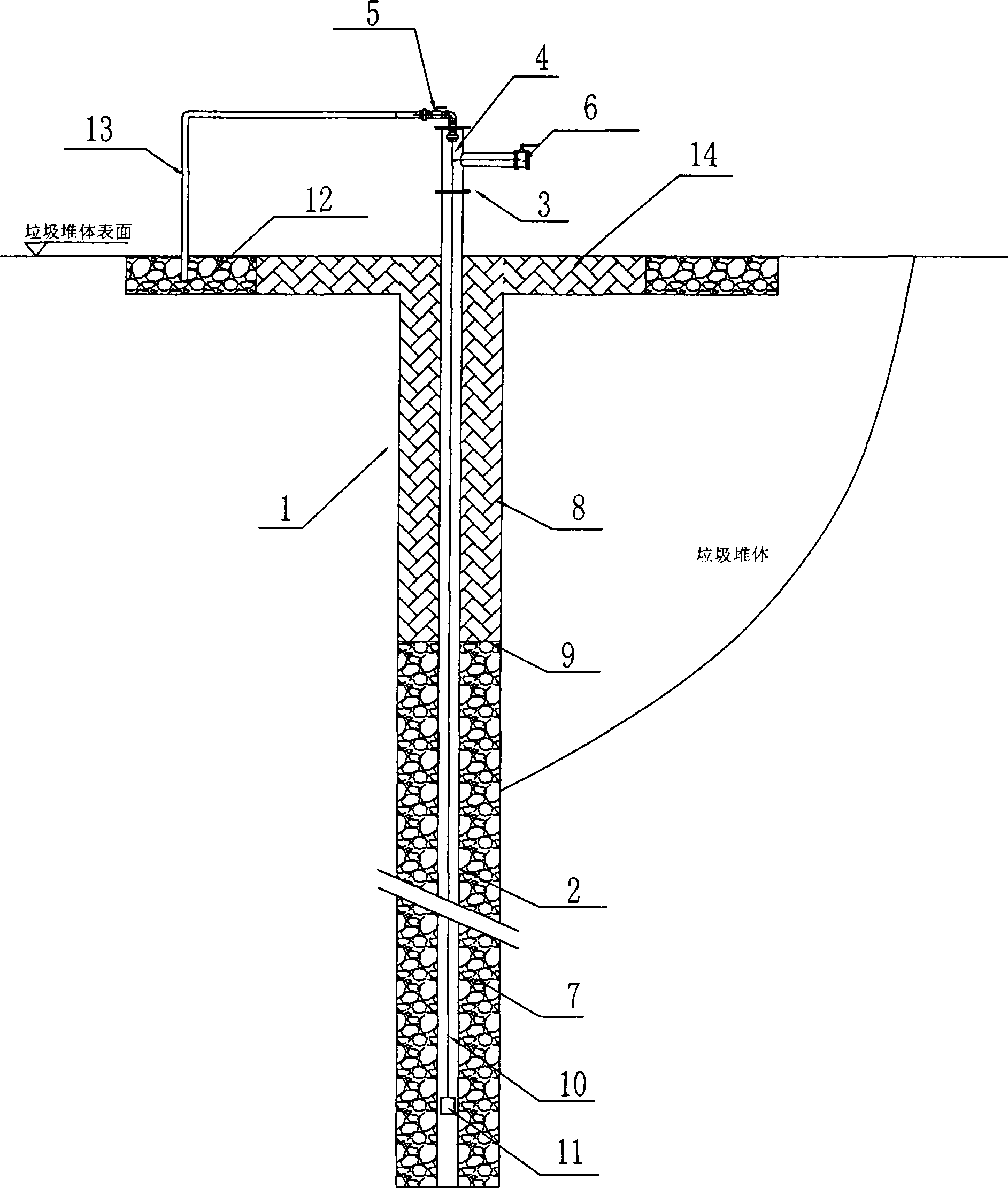
[0020] The present invention will be further described below in conjunction with the accompanying drawings and embodiments.

[0021] Such as figure 1 shown.

[0022] A compound system of gas extraction well and leachate in-situ recharge in landfill, which mainly consists of the following parts:

[0023] A gas extraction shaft 1, the gas extraction shaft 1 is formed by drilling or using a sleeve buried in the garbage dump to follow the garbage dump, with a diameter of 600mm-800mm and a depth of 10m-30m between;

[0024] An air extraction pipe 2, which is installed in the aforementioned air extraction shaft 1, has a diameter of 0.16-0.2 meters; it is made up of a solid wall pipe section of the upper section and a perforated floral pipe section of the lower section, wherein the length of the solid wall pipe section is 2 -3 meters; the upper end of the air extraction pipe 2 protrudes from the ground and is connected with a well head 4 through a flange 3, and a refill valve and ...


PUM


Abstract

The invention relates to an air suction well and percolating liquid original-position recharging compounding system for a refuse landfill field, which is characterized by comprising an air suction drilled shaft, an air suction pipe, a columnar gravel or cobble backfilling layer, a columnar clay backfilling layer, a non-woven fabric layer, a well-internal water discharge pipe, a percolating liquid recharging layer, a recharging pipe, a clay layer for preventing direct recharging. Furthermore, the air suction well and percolating liquid original-position recharging compounding system sucks the percolating liquid through a water discharge pump arranged in the air suction well and recharges the percolating liquid on the spot, thereby not only preventing the refuse landfill field being paved with multiple percolating liquid recharging pipes, but also being beneficial to the degradation of the refuse landfill field and to the increase of the output of landfill gas and the using quantity of the landfill gas of the refuse landfill and effectively decreasing the discharge quantity of the percolating liquid. The invention has the advantages of simple structure, convenient construction, good back percolation effect and low maintenance cost.

Description

technical field [0001] The invention relates to a garbage treatment technology, in particular to a garbage treatment system for improving leachate recharge efficiency in a garbage landfill, in particular to a composite system of an air extraction well and leachate in-situ recharge in a garbage landfill. Background technique [0002] Recharging the leachate produced in the landfill to the landfill can speed up the degradation rate of the landfill. In the past, the leachate drainage system in the landfill was used to pump the leachate back to the surface of the landfill through pipelines for natural seepage. This not only requires a large amount of pipeline materials and water pumps, but also the pipelines laid on the surface of the landfill are likely to interfere with the entry of garbage trucks. In addition, the landfill leachate drainage system is often blocked, causing seepage The filtrate cannot be discharged in time, and the amount of leachate that can be collected is ...

Claims


Application Information

Patent Timeline
Patent Type & Authority Applications(China)
IPC IPC(8): B09B1/00
Inventor 陈泽智龚惠娟吴未立程洋姜茹李亚春
Owner NANJING UNIV
Learn More