Multi-edge shear

A technology of shearing machines and slide rails, which is applied in the direction of shearing devices, shearing machine equipment, and knives used in shearing machine devices, etc., which can solve the problem of difficult matching of the arrangement accuracy of the gripper jaws on both sides of the arrangement accuracy and waste Material sawing process and other issues, to achieve the effect of simple structure, simplified shape, low manufacturing and maintenance costs

Inactive Publication Date: 2009-07-15
NINGBO JIULONG MACHINERY MFG
View PDF1 Cites 6 Cited by
  • Summary
  • Abstract
  • Description
  • Claims
  • Application Information

AI Technical Summary

Problems solved by technology

The cutting of the steel grating in the aforementioned patent still divides the object into three parts, and the waste of material is no less than that of the sawing process
If the above-mentioned patents are to be implemented, it is an insurmountable obstacle that the arrangement accuracy of the steel grating flat steel and the arrangement accuracy of the gripper jaws on both sides are difficult to match

Method used


Image

  • Multi-edge shear
  • Multi-edge shear
  • Multi-edge shear

Examples


Embodiment Construction

[0019] The present invention will be further described in detail below in conjunction with the accompanying drawings and embodiments.

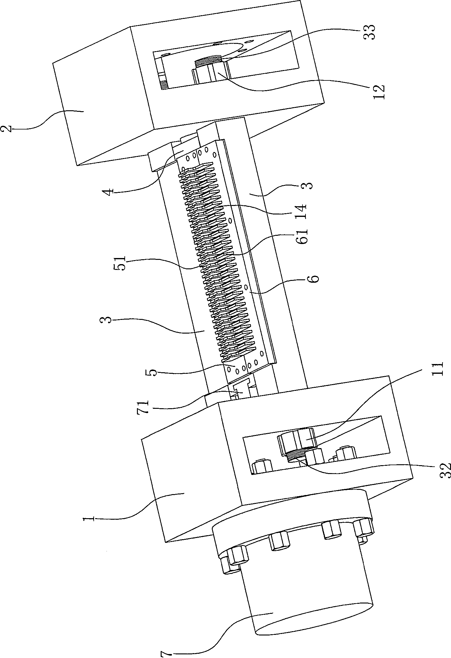
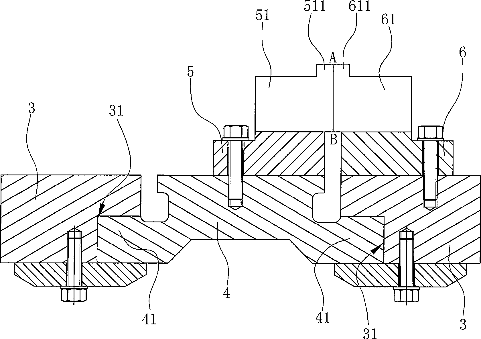
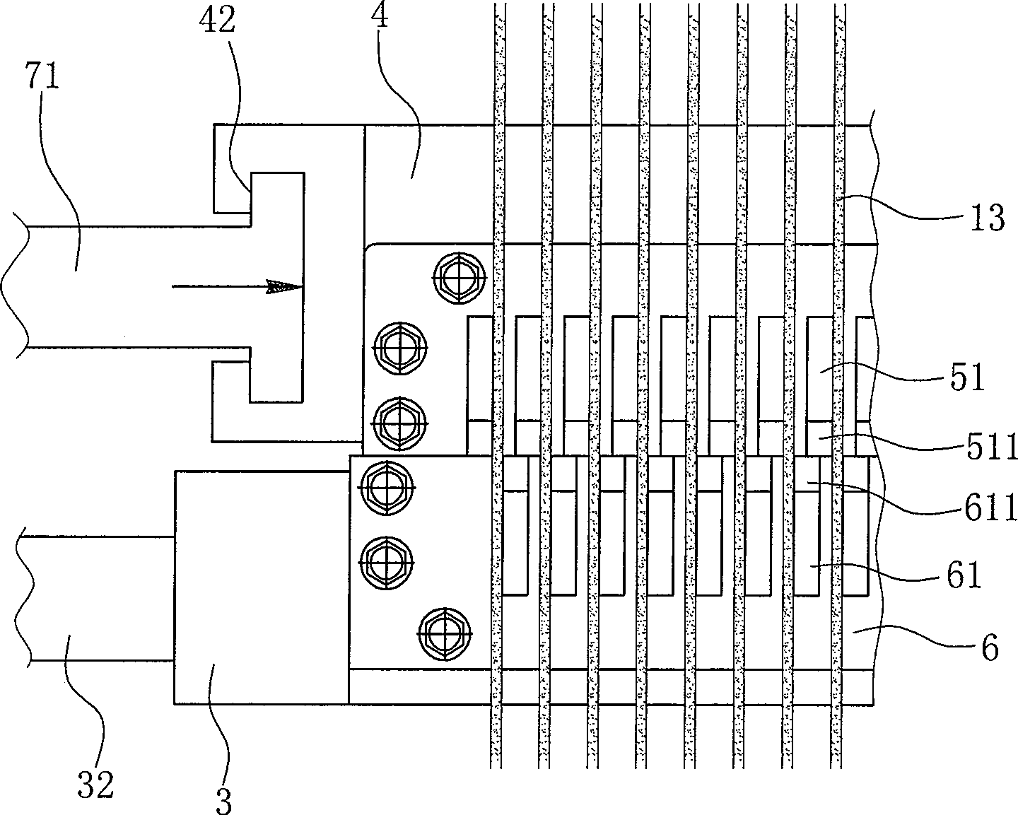
[0020] Such as Figure 1~4 Shown is a preferred embodiment of the present invention.

[0021] A multi-bladed shearing machine, comprising a front wall panel 1 and a rear wall panel 2 spaced apart from each other, the front wall panel 1 and the rear wall panel 2 are directly fixed on the ground, and between the front wall panel 1 and the rear wall panel 2 There are two slide rails 3, the head and tail ends of the two slide rails 3 are respectively fixed to the front wall panel 1 and the rear wall panel 2, the two slide rails 3 are arranged in parallel and spaced apart, and the two ends of each slide rail 3 are threaded. Parts 32, 33, the threaded connection part 32 at one end of the slide rail 3 passes through the inner wall of the front wall panel 1 and is locked with a nut 11, and the threaded connection part 33 at the other end of the slide...


PUM


Abstract

The invention relates to multi-cutting-edge shears, comprising a front wall board and a rear wall board which are mutually separated. The multi-cutting-edge shears are characterized in that two guide ways are parallelly and compartmentally arranged between the front wall board and the rear wall board, a slip block which can reciprocate along a two-guide ways-restrained horizontal direction is restrained between the two guide ways, a moving-blade row with clipboards is arranged on the slip block, a static-blade row with a plurality of clipboards is arranged on one of the guide ways, a hydraulic cylinder is fixed outside the front wall board, the cylinder lever of the hydraulic cylinder is directly connected with the slip block by passing through the front wall board so as to push the slip block and the moving-blade row to move, and the clipboards on the moving-blade row slip with regard to the clipboards on the static-blade row in a misaligned way so as to form a shearing force. The shearing can be carried out as follows: a plurality of strip shaped metal plates are arranged after the strip shaped plow grooves of the two blade rows, and the moving-blade row is driven by the slip block to reciprocate with regard to the static-blade row so as to form the shearing force and shear the strip shaped metal plates. The shearing has no waste material and no pollution to the environment.

Description

technical field [0001] The invention belongs to shearing equipment for metal plates, in particular to a multi-blade shearing machine, which is especially suitable for shearing steel gratings. Background technique [0002] All kinds of metal plates, especially steel gratings, are widely used in working platforms, pedals, plank roads, guardrails, etc. in many industries. The steel grating is made of multiple rows of load flat steel and multiple rows of cross bars arranged at a certain distance in warp and weft to form a grid shape. The warp direction is the load flat steel, that is, the length direction of the steel grating. is the cross bar, that is, the width direction of the steel grating. The steel grating is welded by the above-mentioned multi-row strip steel plate bearing the main load and the multi-row horizontal twisted steel perpendicular to it through the automatic pressure welding machine. The area of ​​the welded steel grating is very large, and it needs to be Us...

Claims


Application Information

Patent Timeline
Patent Type & Authority Applications(China)
IPC IPC(8): B23D15/08B23D15/14B23D35/00
Inventor 潘正利范大勇胡因亮
Owner NINGBO JIULONG MACHINERY MFG
Why Eureka
Try Eureka