Light intensity correcting method for arranging annular light intensity monitoring section around interferogram

A light intensity monitoring and interferogram technology, applied in optical radiation measurement, optics, measuring devices, etc., to achieve the effect of improving light intensity correction accuracy and simple hardware system

Inactive Publication Date: 2009-07-15
BEIJING INSTITUTE OF TECHNOLOGYGY
View PDF0 Cites 0 Cited by
  • Summary
  • Abstract
  • Description
  • Claims
  • Application Information

AI Technical Summary

Problems solved by technology

[0005] The technical problem to be solved by the present invention is how to directly extract the sampling light from the interferogram acquisition optical path, and accurately correct the influence of laser light intensity drift and other factors on the interferogram light intensity without adding complex optical paths or detectors, so as to improve the interference measurement accuracy

Method used


Image

  • Light intensity correcting method for arranging annular light intensity monitoring section around interferogram

Examples


Embodiment Construction

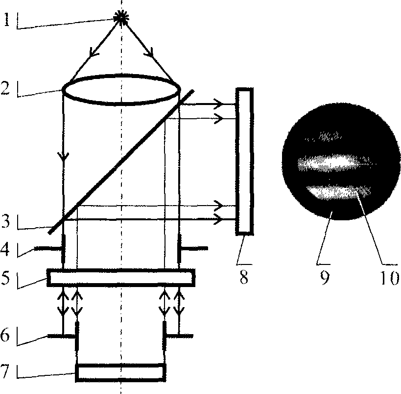
[0022] The present invention is especially suitable for the Fizeau type interferometer, because in this interferometer, the measurement light and the reference light are also almost completely in the same path, only the light path between the reference surface and the measured surface is unique to the measurement light path, and the light intensity is corrected. Higher precision. Taking a typical Fizeau interferometer as an example, its optical path is as follows figure 1 shown. The laser light emitted by the light source 1 is collimated by the collimating lens 2, and then enters the semi-transparent and semi-reflective reference mirror 5 through the beam splitter 3, and the reflected light on the rear surface is used as the reference light, and the transmitted light is incident on the measured mirror 7. Generally, Fizeau interferometers make full use of the apertures of the reference mirror and the mirror under test to form an interferogram, and measure the full aperture of ...


PUM


Abstract

The invention relates to a light intensity correction method by cutting out a circular light intensity monitoring area on the outer ring of the interferogram, which comprises the following steps: 1, adding a the aperture diaphragm of the tested piece, and converting the outermost ring shaped part into light intensity monitoring area directly; 2, recording the light intensity in the light intensity monitoring area while recording the interferogram by the only image detector in the system; 3, processing the image to obtain light intensity correction coefficient, processing the light intensity in the light intensity monitoring area before processing the sequential interferogram to abstract the light intensity correction coefficient; 4, correcting the light intensity of the interferogram by the light intensity correction coefficient. the invention can accomplish the monitoring light detection while recording interferogram only by adding the aperture diaphragm of the tested piece into classic interferometer, neither change the light path mode nor adds complex component or sub light path, and has a very simple hardware system; it maintains the tested aperture furthest while acquiring enough light intensity correction information by adopting the outer ring light intensity monitoring area.

Description

technical field [0001] The invention relates to laser interferometry technology, the purpose of which is to simply, accurately and real-timely correct the light intensity change of the interferogram caused by laser light intensity drift, etc. . Background technique [0002] Laser interferometry is a photoelectric measurement method that uses the coherence of laser light to process the information reflected by the phase change. Since light is a high-frequency electromagnetic wave, it is difficult to directly observe its phase change, so it is much easier to observe it by using interference technology to convert the phase difference into the change of light intensity. Usually, by using the interference between the reference light of the reference reflective surface and the measuring light reflected by the measured object, the distance of the measured object and the surface shape and other parameters can be measured non-contact, and the measurement accuracy is generally on the...

Claims


Application Information

Patent Timeline
Patent Type & Authority Applications(China)
IPC IPC(8): G01B9/02G01J9/02G02B27/00
Inventor 郝群朱秋东胡摇汤磊
Owner BEIJING INSTITUTE OF TECHNOLOGYGY
Why Eureka
Try Eureka