
Thyristor electronic board for failure current limiter

A thyristor electronic board and fault current technology, applied in the field of power systems, can solve problems such as poor anti-interference ability, monitoring signal transmission, and increased leakage reactance, and achieve strong anti-electromagnetic interference ability, strong anti-interference ability, and high stability Effect

Inactive Publication Date: 2009-07-15
CHINA ELECTRIC POWER RES INST +1
View PDF0 Cites 14 Cited by
  • Summary
  • Abstract
  • Description
  • Claims
  • Application Information

AI Technical Summary

Problems solved by technology

[0003] Since this method uses a pulse transformer to achieve high and low potential isolation and signal transmission, it has the following inevitable disadvantages: (1) The leakage inductance in the pulse transformer circuit will greatly reduce the steepness of the rising edge of the trigger pulse, especially When the voltage level is high, in order to ensure that the pulse transformer has sufficient insulation capacity, the leakage reactance of the primary and secondary sides will greatly increase, which will further cause the steepness of the leading edge of the trigger pulse to decrease, which is extremely important for the simultaneous triggering of the thyristor strings in the high-voltage valve. Adverse
(2) The distributed capacitance of the primary and secondary sides of the pulse transformer forms a high-frequency interference channel. When the valve is commutated or lightning strikes, it is easy to cause false triggering, so its anti-interference ability is poor
(3) When the voltage level is very high, it is difficult for the electromagnetic trigger method to accurately transmit the monitoring signal to the low potential, so it is difficult to realize the on-line monitoring of the thyristor

Method used


Image

  • Thyristor electronic board for failure current limiter
  • Thyristor electronic board for failure current limiter
  • Thyristor electronic board for failure current limiter

Examples


Embodiment Construction

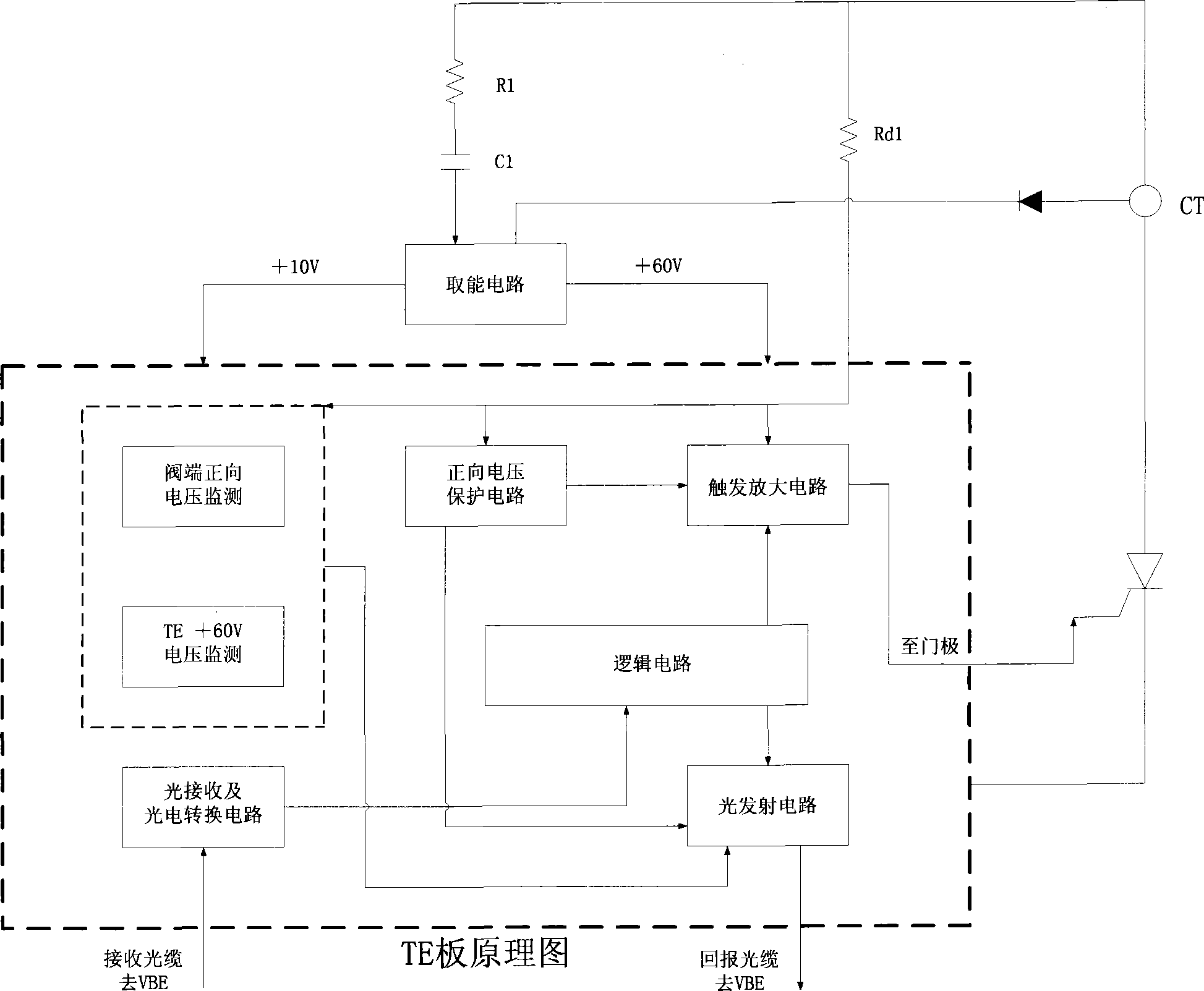
[0027] Thyristor electronic board TE principle as technical attachment image 3 . The technical solution is as follows:

[0028] (1) Thyristor triggering and online monitoring

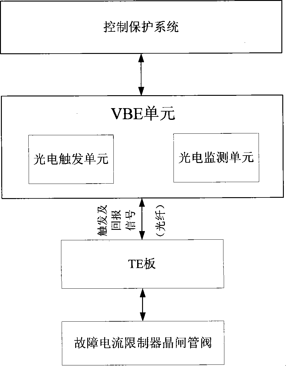
[0029] The fault current limiter is put into operation only when the transmission line is short-circuited, so the fault current limiter is in the waiting state for a long time. In order to ensure the reliable operation of the fault current limiter, the thyristor electronic board TE monitors the state of the thyristor in real time during the waiting state and thyristor electronic board TE's own power supply status, determined by the attached image 3 Middle valve terminal voltage monitoring and thyristor electronic board TE+60V power supply monitoring circuit are realized. Each cycle is 20ms. The valve-based electronic equipment VBE sends monitoring pulses to the thyristor electronic board TE through a high-voltage optical cable. After passing through the light receiving and photoelectric conversion ...


PUM


Abstract

The present invention provides a failure current limitator thyristor electronic board. The thyristor electronic board TE provided in the invention has the following functional characteristics: 1) strong anti-electromagnetic interference capability; 2) the thyristor electronic board TE has low power consumption; 3) special thyristor trigger and on-line monitor method are adopted. The organic combination of these functional characteristics can realize failure current limitator thyristor valve trigger and on-line monitoring perfectly with reliable operation, high stability and strong anti-interference capability.

Description

technical field [0001] The invention relates to the field of power systems, in particular to a thyristor electronic board for a fault current limiter. Background technique [0002] With the development of power electronic devices and the maturity of optoelectronic technology, the thyristor valve trigger and online monitoring system has also experienced tremendous development. Early thyristor valve triggering and monitoring were almost electromagnetic. That is, the ground potential device directly applies the trigger signal to the gate of the thyristor through the pulse transformer to trigger the thyristor. The electrical isolation device between ground potential equipment and high potential equipment is a pulse transformer. [0003] Since this method uses a pulse transformer to achieve high and low potential isolation and signal transmission, it has the following inevitable disadvantages: (1) The leakage inductance in the pulse transformer circuit will greatly reduce the s...

Claims


Application Information

Patent Timeline
IPC IPC(8): H02H9/02H02H9/08
Inventor 王华锋蓝元良于海玉栾洪州王华昕
Owner CHINA ELECTRIC POWER RES INST
Learn More