

Control system for multiphase electric rotating machine
A technology for rotating electrical machines and control systems, applied in the field of control systems, can solve problems such as circuit complexity
- Summary
- Abstract
- Description
- Claims
- Application Information
AI Technical Summary
Problems solved by technology
Method used
Image

Examples
no. 1 example
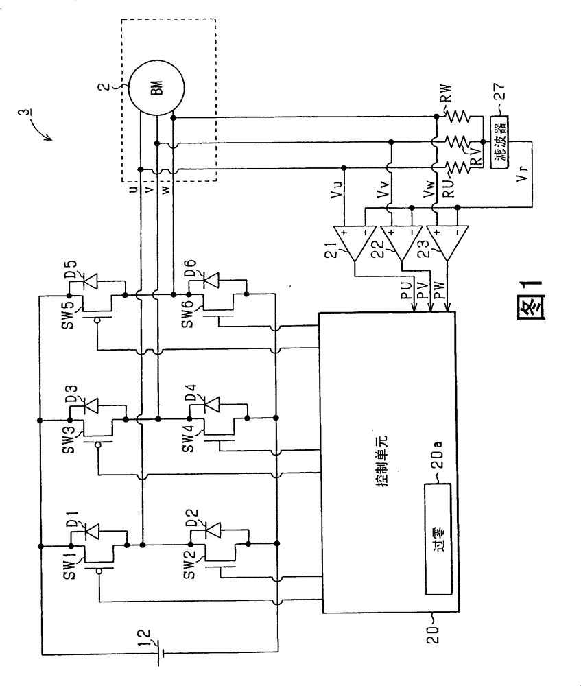
[0049] first reference figure 1 , the brushless motor 2 is a three-phase motor with a permanent magnet as a rotor, and is used as an actuator for a fuel pump of an onboard internal combustion engine. Three phases (U phase, V phase, W phase) of the brushless motor 2 are connected to a power conversion circuit 3 such as an inverter which is a power converter from direct current to alternating current. The power conversion circuit 3 is a three-phase power conversion circuit, and appropriately applies the voltage on the battery 12 side to the three phases of the brushless motor 2 . Specifically, the power conversion circuit 3 has a parallel connection circuit including switching elements SW1, SW2, switching elements SW3, SW4, and switching elements SW5, SW6 so that each of the three phases is connected to the positive electrode side or the negative electrode side of the battery 12. The electrode side is turned on. A connection point connecting the switching element SW1 and the s...
no. 2 example
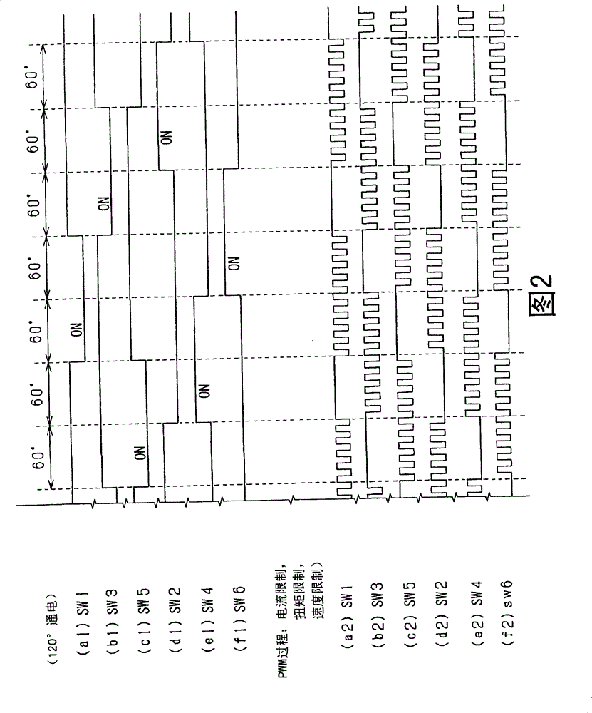
[0085] exist Figure 8 In the second embodiment shown in , the power conversion circuit 3 is constructed in the same manner as in the first embodiment, and the control unit 20 controls the brushless DC motor 2 by operating the power conversion circuit 3 . In this example, switching control is basically performed by a 120° energization method. Specifically, the timing at which the induced voltage becomes the neutral point voltage (reference voltage Vr) of the brushless motor 2 is detected using the timing at which the induced voltage appears in the terminal voltages Vu, Vv, and Vw of the corresponding phases of the brushless motor 2 (zero crossing moment). Assume that the reference voltage Vr is provided by dividing the terminal voltages Vu, Vv, and Vw of the corresponding phases of the brushless motor 2 through the resistance elements RU, RV, and RW. Assuming that the zero-crossing timing is the inversion timing of the outputs of the comparators 21, 22 and 23, the comparator...
no. 3 example
[0108] In the third embodiment, for example, as Figure 13 As shown, the starting process of the brushless motor 2 is repeatedly executed by the control unit 20 at a given cycle.
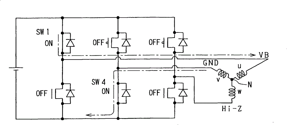
[0109] In this series of processing, first, the first positioning process is performed in S30. The first positioning process controls the target angle to the first positioning target angle by allowing current to flow from one specific phase of the brushless motor 2 to the remaining two phases. According to the energization method described above, since the force for reducing the phase shift of the rotation angle of the brushless motor 2 from the first positioning target angle is applied, the convergence time of the first positioning target angle can be reduced. Therefore, the time for performing the first positioning process (first required time T1) is adjusted based on the time at which the magnitude of rotation angle variation is shorter than the angular interval between the first positioning tar...
PUM
 Abstract
Description
Claims
Application Information