Radiation type heating board structure for electronic product annealing and sintering furnace

A technology of electronic products and radiant panels, which is applied in the direction of furnace heating elements, lighting and heating equipment, furnaces, etc., can solve the problems of unfavorable annealing or sintering, unevenness, etc., and achieve the effects of uniform temperature, uniform heating, and improved quality

Inactive Publication Date: 2009-07-15
SUZHOU HUIKE EQUIP CO LTD
View PDF0 Cites 7 Cited by
  • Summary
  • Abstract
  • Description
  • Claims
  • Application Information

AI Technical Summary

Problems solved by technology

However, inhomogeneity will appear during the heating of the radiant plate by the heating element, because the temperature in the middle of the radiant plate is usually higher than that on both sides, so that the temperature of the furnace also shows a phenomenon that the middle is high and the sides are low, which affects the annealing of the product. or unfavorable sintering

Method used


Image

  • Radiation type heating board structure for electronic product annealing and sintering furnace
  • Radiation type heating board structure for electronic product annealing and sintering furnace

Examples


Embodiment 1

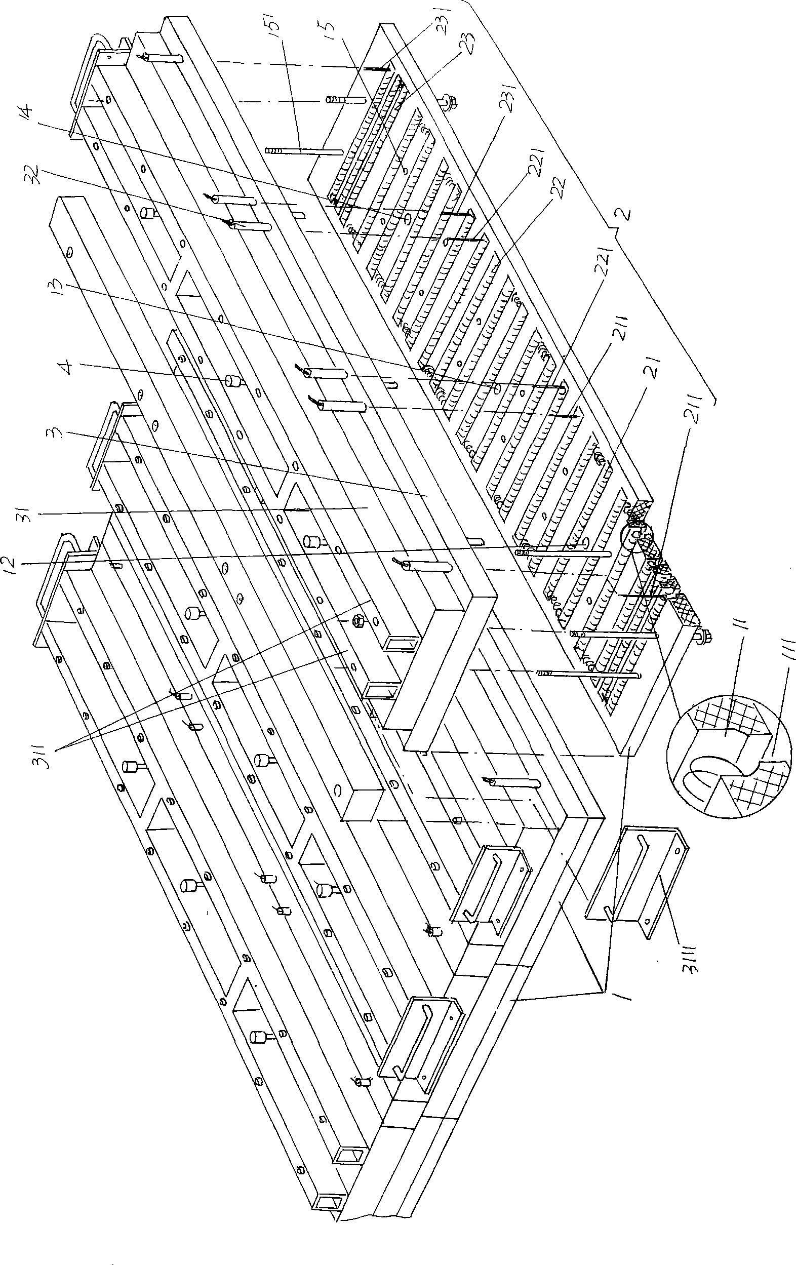
[0021] See figure 1 According to common knowledge, the length of the furnace body of an annealing and sintering furnace for electronic products is long or short, ranging from several meters to tens of meters, and ranging from tens to hundreds of meters. Therefore, the radiant panel body 1 has a width determined The number of cases also changes accordingly. Since the structure of each radiant panel body 1 provided by the technical solution of the present invention is the same, although five are shown in the figure, the applicant chooses one to describe in detail below. description of.

[0022] The radiant panel body 1 is made of ceramic fiber board, and the radiant panel body 1 is provided with electric heating wire slots 11, wherein the electric heating wire slots 11 located at the left and right ends of the radiant panel body 1 The spacing is smaller than the spacing of the electric heating wire slots 11 at other positions. In this embodiment, the electric heating wire slot...

Embodiment 2

[0026] The figure is omitted, the electric heating wire slot 11 is processed into a U shape, and the notch 111 in Embodiment 1 is omitted. This solution can prevent the oxidation of the first, second, and third electric heating wires 21, 22, and 23 surfaces. Objects fall into the furnace to pollute the product, and the furnace is kept clean. All the other are the same as the description to embodiment 1.

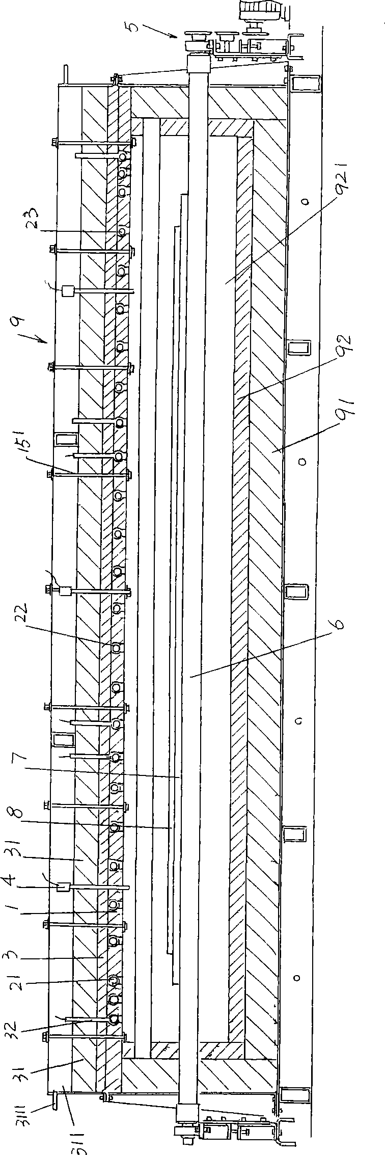
[0027] please see figure 2 , this figure has provided the sectional shape of the body of furnace 9 of electronic product annealing furnace or sintering furnace, and the interior of body of furnace heat insulating layer 91 is furnace 92, and the conveying roller 6 in the hearth 921 of furnace 92 is provided with supporting plate 7 Place the plasma display panel 8 as an electronic product on the supporting plate 7, and the radiant panel body 1 of the present invention is fixed on the furnace hearth 921 top of the body of heater 9 by a group of bolts 151 carrying the insulatio...


PUM


Abstract

The invention provides a radiation type heating plate structure of an electronic product for anneal or welding furnace which belongs to the electrical heating equipment of anneal or welding furnace technique field. The structure includes a radiation plate body and a heating body laid on the radiation plate body which has characteristics that the heating body includes a first electric heating filament, a second electric heating filament, a third electric heating filament, the first electric heating filament is laid on one end of the radiation plate body along length direction, the third electric heating filament is laid on another end of the radiation plate body along length direction, the second electric heating filament locates between the first electric heating filament and the second heating filament, wherein, the first, second and third electric heating filament constitute an independence electric heating circuit respectively. The structure has advantages that the structure can avoid state of low middle temperature and high ends temperature of the radiation plate, the radiation plate is heated evenly for ensuring even temperature in left, middle and right parts of the welding furnace which is help for improving quality of anneal or welding to the electronic product.

Description

technical field [0001] The invention belongs to the technical field of electric heating facilities for annealing or sintering furnaces, and in particular relates to a radiation heating plate structure for annealing or sintering furnaces of electronic products. Background technique [0002] In the production process of many electronic components, annealing or sintering is an essential step and is a key step. For example, the manufacture of plasma display must rely on annealing or firing furnace, plasma display (also known as plasma display panel) )’s English abbreviation is PDP, and its full English name is Plasma Display Panel. It is a component that injects mixed gas between two ultra-thin glass plates and applies voltage to use phosphor to emit light. Compared with CRT picture tube displays , has the characteristics of high resolution, large screen, ultra-thin and light, rich and vivid colors; compared with LCD, it has the characteristics of high brightness, good contrast,...

Claims


Application Information

Patent Timeline
IPC IPC(8): H05B3/62H05B3/66F27B21/08
Inventor 惠文彬
Owner SUZHOU HUIKE EQUIP CO LTD
Why Eureka
Try Eureka