Welding robot

A welding robot and welder technology, which is applied in welding equipment, manipulators, arc welding equipment, etc., can solve the problems of weld seam tracking not being able to function effectively, effort, error, etc., to achieve efficient tracking and prevent human errors Effect

Active Publication Date: 2009-07-22
KOBE STEEL LTD
View PDF1 Cites 77 Cited by
  • Summary
  • Abstract
  • Description
  • Claims
  • Application Information

AI Technical Summary

Problems solved by technology

In order to reduce the correction amount due to tracking, not only the machining accuracy of the workpiece to be welded must be improved, but also the manufacturing aspects such as minimizing the positional deviation during installation and welding thermal deformation must be spent, which leads to the inherent cost of correcting these errors. The purpose is that seam tracking cannot function effectively as a result
[0006] Second, the operation is troublesome and becomes the cause of human error
However, in this method, when the program is executed, the operator is forced to sequentially input which electrode to select while grasping the traveling direction of welding.
In addition, there is also the possibility of an illegal tracking method that is selected for tracking based on the current change value of the subsequent electrode due to an input error

Method used


Image

  • Welding robot
  • Welding robot
  • Welding robot

Examples


no. 1 approach

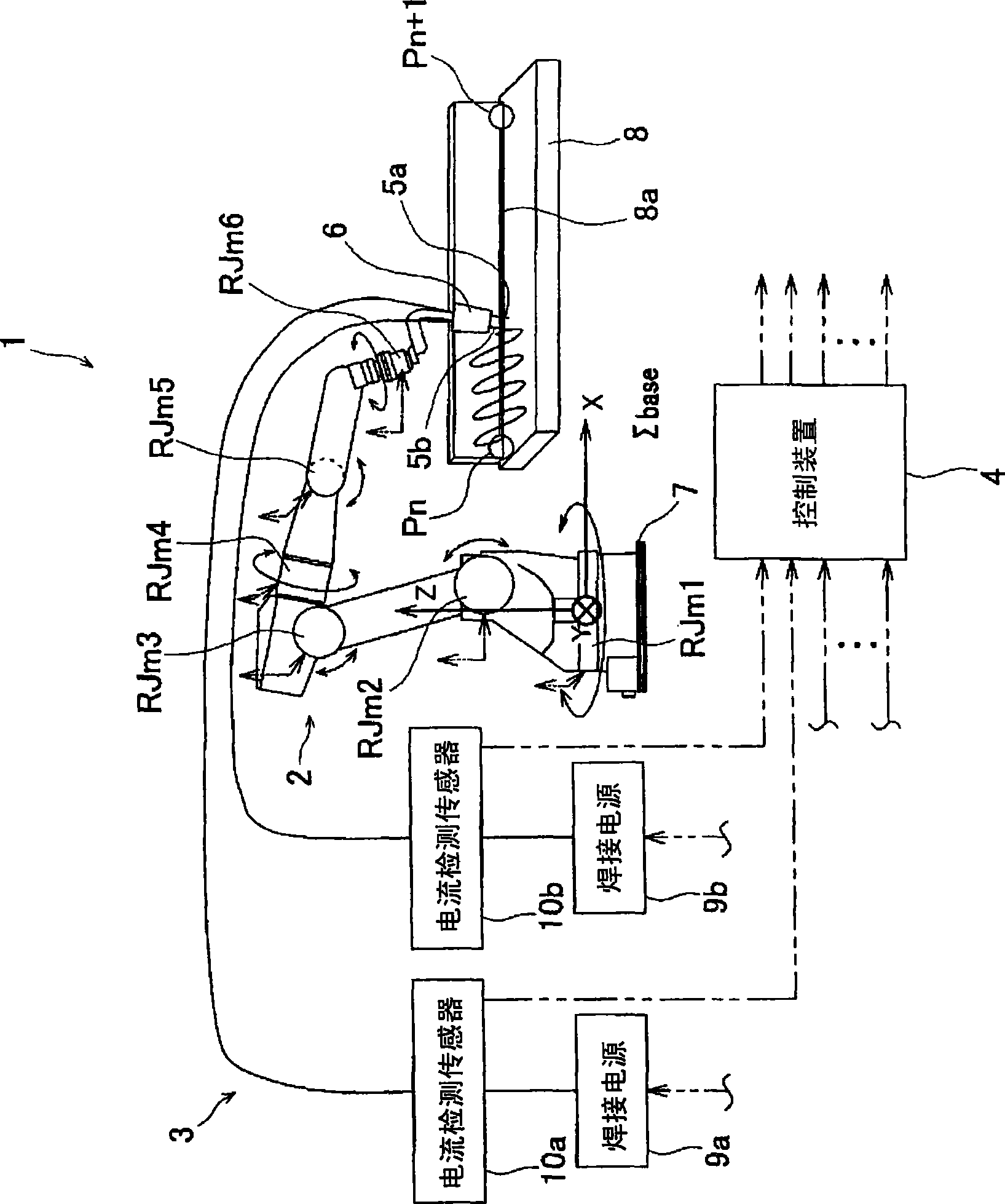
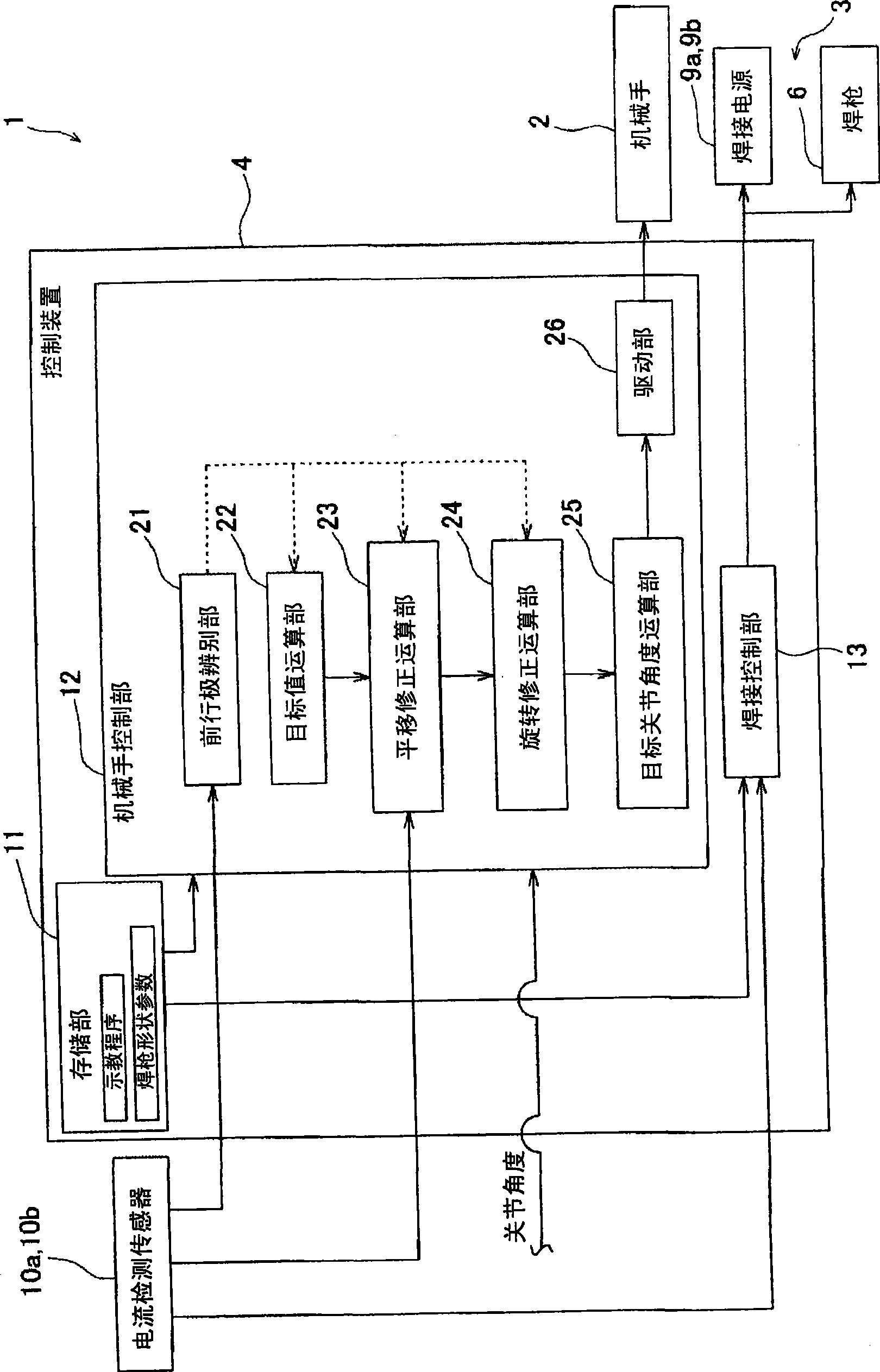
[0066] figure 1 The shown welding robot 1 according to the first embodiment of the present invention includes a manipulator 2 , a welder 3 , and a control device 4 . This welding robot 1 automatically welds a workpiece (object to be welded) 8 along a welding joint 8a.

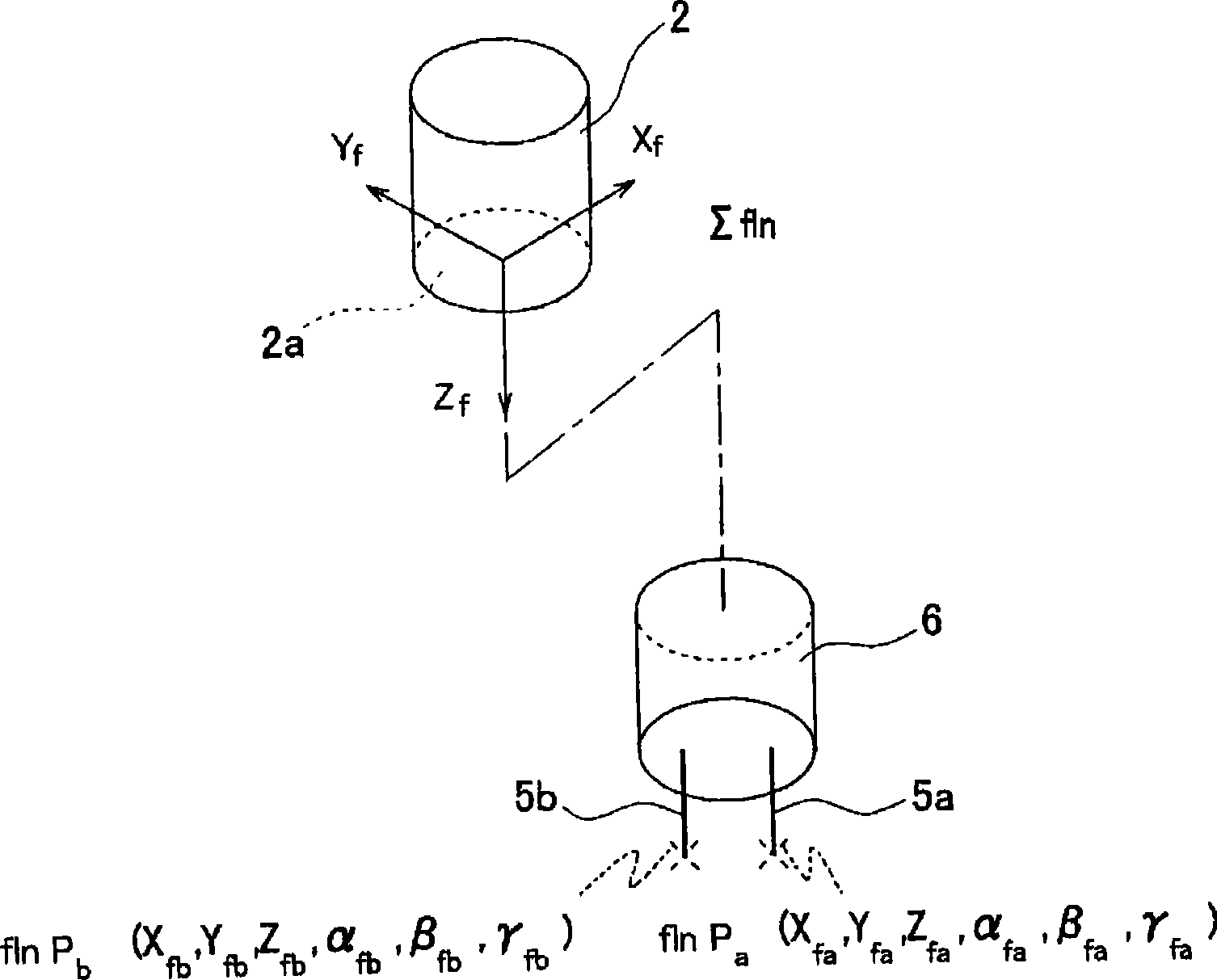
[0067] On the flange surface 2a at the front end of the manipulator 2 (refer to image 3 ) is mounted with a pair of arc electrodes (hereinafter, simply referred to as "electrodes") 5a, 5b made of copper wires, and a tandem type torch 6 is attached. The manipulator 2 changes the position and posture of the welding torch 6 in three-dimensional space. Manipulator 2 has six rotary joints, namely RJm1, RJm2, RJm3, RJm4, RJm5, RJm6. The revolving joints RJm1 to RJm6 are connected by a link, and the bottommost revolving joint RJm1 is attached to the pedestal 7 . Each of the revolving joints RJm1 to RJm6 includes an angle sensor for detecting a motor joint angle J ( J1 , J2 , J3 , J4 , J5 , J6 ) for rotational dr...

no. 2 approach

[0120] Such as Figure 10 and Figure 11 The shown welding robot 1 of the second embodiment of the present invention is provided with alternative current detection sensors 10a, 10b (refer to figure 2 and figure 1 ) of the optical sensor 100. The optical sensor 100 includes: a condenser 101 ; and a light receiving sensor 102 . In addition, in the present embodiment, the forward electrode can be known in advance (hereinafter, the electrode 5 a is referred to as the forward electrode).

[0121] Such as Figure 12A and Figure 12B The shown control of the manipulator 2 by the control device 4 is the same as that of the first embodiment in that after moving to the welding start position Pn and starting welding (steps S12-1, S12-2), the target of the forward electrode 5a The calculation of the value Plead(t) uses the calculation of the primary correction target value Plead(t)' using the translation correction amount ΔP(t), and the secondary correction target value Plead(t)" ...


PUM


Abstract

The invention provides a welding robot which makes it possible to, in a seam tracking operation during tandem welding, realize a high tracking ability, not only for a leading electrode, but also for a trailed electrode. A translational correction calculating unit (23) corrects a target value Plead(t) of the leading electrode (5a) using a translational correction amount Delta P(t) in a base coordinate system Sigmabase for a next time position of the leading electrode (5a), to obtain a primary correction target value Plead(t)'. A rotational correction calculating unit (24) calculates a rotation correction amount Delta theta(t) for correcting displacement of an orientation of a torch (6) around the leading electrode (5a) with respect to a actual weld line Lre generated because of the translational correction amount Delta P(t), and calculates a secondary correction target value Plead(t)'' resulting from correcting the primary correction target value Plead(t)' so that the torch (6) rotates around the leading electrode (5a) by the rotation correction amount Delta theta(t). A manipulator (2) is driven on the basis of the secondary correction target value Plead(t)''.

Description

technical field [0001] The invention relates to a welding robot. More specifically, the present invention relates to a welding robot that performs seam tracking in tandem welding. Background technique [0002] For automatic welding equipment such as welding robots, "Seam Tracking" that automatically tracks weld seams with various sensors is widely used. The purpose of seam tracking is to prevent welding defects by detecting and correcting the deviation of the welding target position due to machining errors, setting errors, and dynamic errors of the welding process caused by thermal deformation, etc. . Figure 13 Schematic representation of the principle of seam tracking. As the sensor 1 used, there are a mechanical sensor, a sensor using a change in arc welding current, an optical-visual sensor, and the like. Even though the sensor 1 has different methods, the principle is the same from the following point of view, that is, the signal measured by the sensor 1 is processed...

Claims


Application Information

Patent Timeline
Patent Type & Authority Applications(China)
IPC IPC(8): B23K9/127
CPCB23K9/1272B23K9/095B23K9/127B25J9/06B25J9/16
Inventor 西村利彦重吉正之
Owner KOBE STEEL LTD
Why Eureka
Try Eureka