Cutterhead apparatus for automatic cutting machine

A technology of cutting machine and cutter head, which is applied in the cutting, application, leather punching/punching/cutting of textile materials, etc. It can solve the problems of cutter breaking, affecting work efficiency, and not being able to maintain the cutter, so as to increase the service life , improve production efficiency, simple structure effect

Inactive Publication Date: 2009-07-22
SHAGNHAI YIN SCI&TECH CO LTD
View PDF0 Cites 9 Cited by
  • Summary
  • Abstract
  • Description
  • Claims
  • Application Information

AI Technical Summary

Problems solved by technology

At present, there are some defects in the cutter head device of the traditional automatic cutting machine, and the technical structure of the cutter head device. Up and down linear reciprocating motion is in a state of dynamic balance
It is easy to break the cutter, which will affect the work efficiency

Method used


Image

  • Cutterhead apparatus for automatic cutting machine
  • Cutterhead apparatus for automatic cutting machine
  • Cutterhead apparatus for automatic cutting machine

Examples


Embodiment Construction

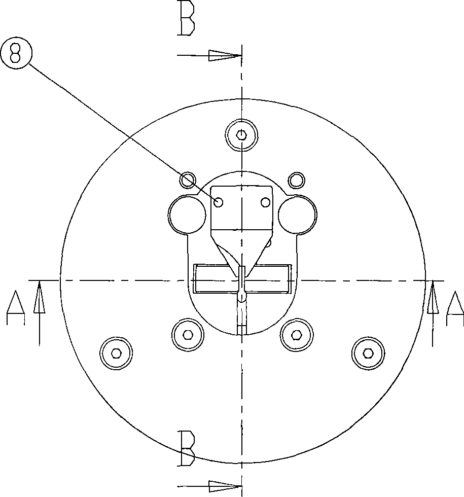
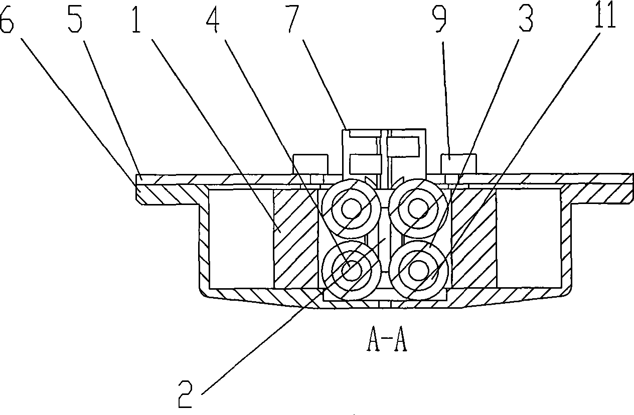
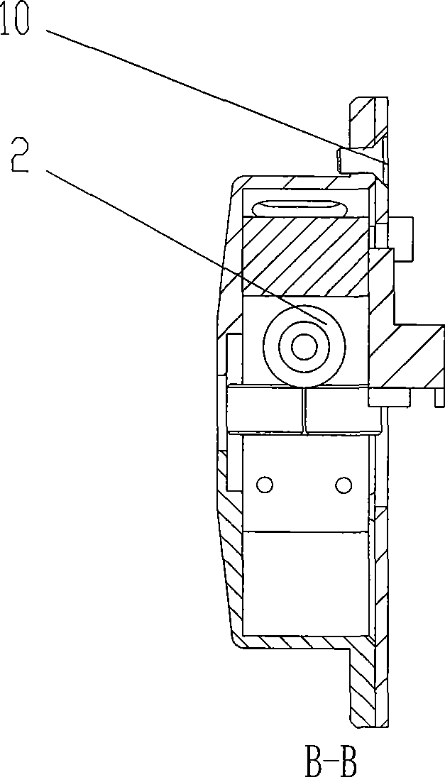
[0018] like Figure 1 to Figure 4 As shown, the present invention is used for the cutterhead device of automatic cutting machine, comprises cutterhead box 6, cutterhead cover 5, and flat grinding wheel 3, convex grinding wheel 2 and block 1 are installed in cutterhead box 6, flat grinding wheel 3 and The cam grinding wheel 2 is installed in the block 1 through the small shaft 4 , and the cam grinding wheel 2 is installed in the block 1 through the bearing 11 . Flat grinding wheel 3 is provided with four groups, and convex grinding wheel 2 is provided with one group, and four groups of flat grinding wheels 3 are arranged in two rows up and down, and every row is arranged side by side in two groups, and convex grinding wheel is located at the position between four groups of flat grinding wheels. Four sets of flat grinding wheels are combined with one set of convex grinding wheels and installed in the sipe block. It can keep the cutting knife in a state of dynamic balance for up...


PUM


Abstract

The invention discloses a cutterhead device for an automatic cutting machine. The cutterhead device comprises a cutterhead box and a cutterhead cover; the inside of the cutterhead box is provided with flat grinding wheels, convex grinding wheels and a saddle; and the flat grinding wheels and the convex grinding wheels are arranged inside the saddle by a small shaft and a bearing. The flat grinding wheels are provided with four sets; the convex grinding wheels are provided with one set; four sets of the flat grinding wheels are arranged in an upper row and a lower row, and each row is provided with two sets in parallel; and the convex grinding wheels are arranged in the positions between four sets of the flat grinding wheels. The cutterhead device has the advantages that the device has simple structure and accurate guide function, and improves working efficiency.

Description

technical field [0001] The invention relates to a cutter head device, in particular to a cutter head device of an automatic cutting machine. Background technique [0002] The cutter head device is a device that keeps the cutting knife in a dynamic balance state during the up and down linear reciprocating motion during the operation of the automatic cutting machine. At present, there are some defects in the cutter head device of the traditional automatic cutting machine, and the technical structure of the cutter head device. The up and down linear reciprocating motion is in a state of dynamic balance. It is easy to break the cutter, which affects work efficiency. A cutter head device with simple structure, precise guiding function and improved work efficiency is urgently needed in modern production and processing. Contents of the invention [0003] The technical problem to be solved by the present invention is to overcome the shortcomings of the prior art. The present in...

Claims


Application Information

Patent Timeline
Patent Type & Authority Applications(China)
IPC IPC(8): B26D7/08B26D1/06C14B5/00D06H7/00
Inventor 尹智勇
Owner SHAGNHAI YIN SCI&TECH CO LTD
Why Eureka
Try Eureka