Three-axial vibration composite testing apparatus

一种复合试验、轴向振动的技术,应用在振动测试、测量装置、机器/结构部件的测试等方向,能够解决影响刚性、增加运动部件质量、运动部质量大等问题,达到提高抗倾覆力矩的能力、减少中间立方体、降低制造的难度的效果

Active Publication Date: 2009-07-22
SUZHOU SUSHI TESTING INSTR CO LTD
View PDF2 Cites 37 Cited by
  • Summary
  • Abstract
  • Description
  • Claims
  • Application Information

AI Technical Summary

Problems solved by technology

[0008] 1. In terms of manufacturing, since the three axes adopt hydrostatic bearing structure, the structure is relatively complex, and the processing requirements of each matching plane are high and difficult, and the manufacturing cost is high
[0009] 2. In terms of vibration test performance, because the middle cube 7 of a certain height needs to be set under the working table 1 to arrange the pressure application plate 8, this increases the distance from the working table 1 to the vibration generator 2 on the vertical axis (that is, raising The working surface 1) has been affected to a certain extent; because the middle cube 7 and multiple pressure application plates 8 need to be set under the working surface 1, the quality of the moving parts has been increased; the rigidity is poor and the mass of the moving part is large. These two points directly limit the further improvement of the working frequency; moreover, the elevation of the working surface 1 also directly leads to the decline of the ability to resist overturning moment

Method used


Image

  • Three-axial vibration composite testing apparatus
  • Three-axial vibration composite testing apparatus
  • Three-axial vibration composite testing apparatus

Examples


Embodiment 1

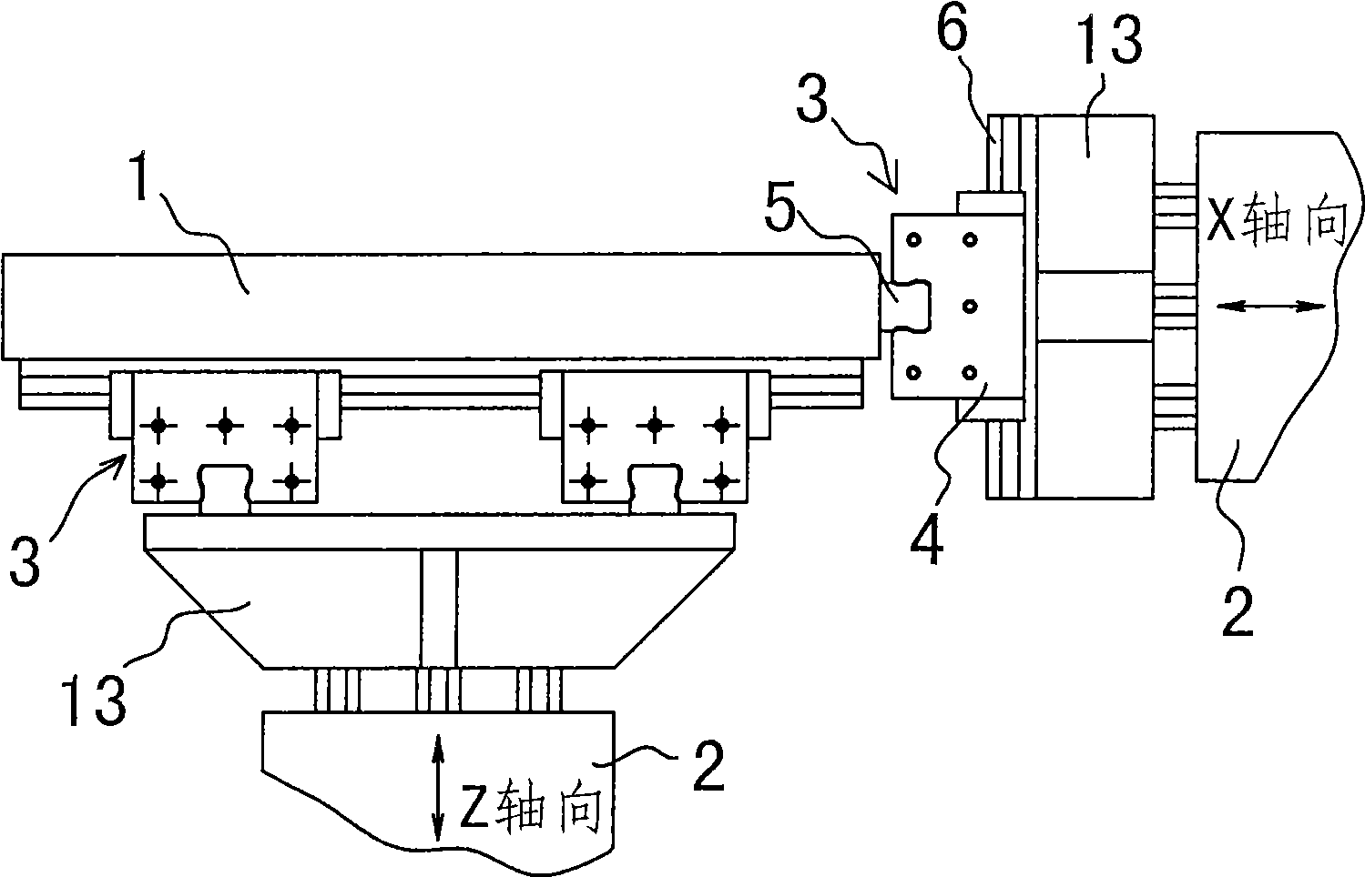
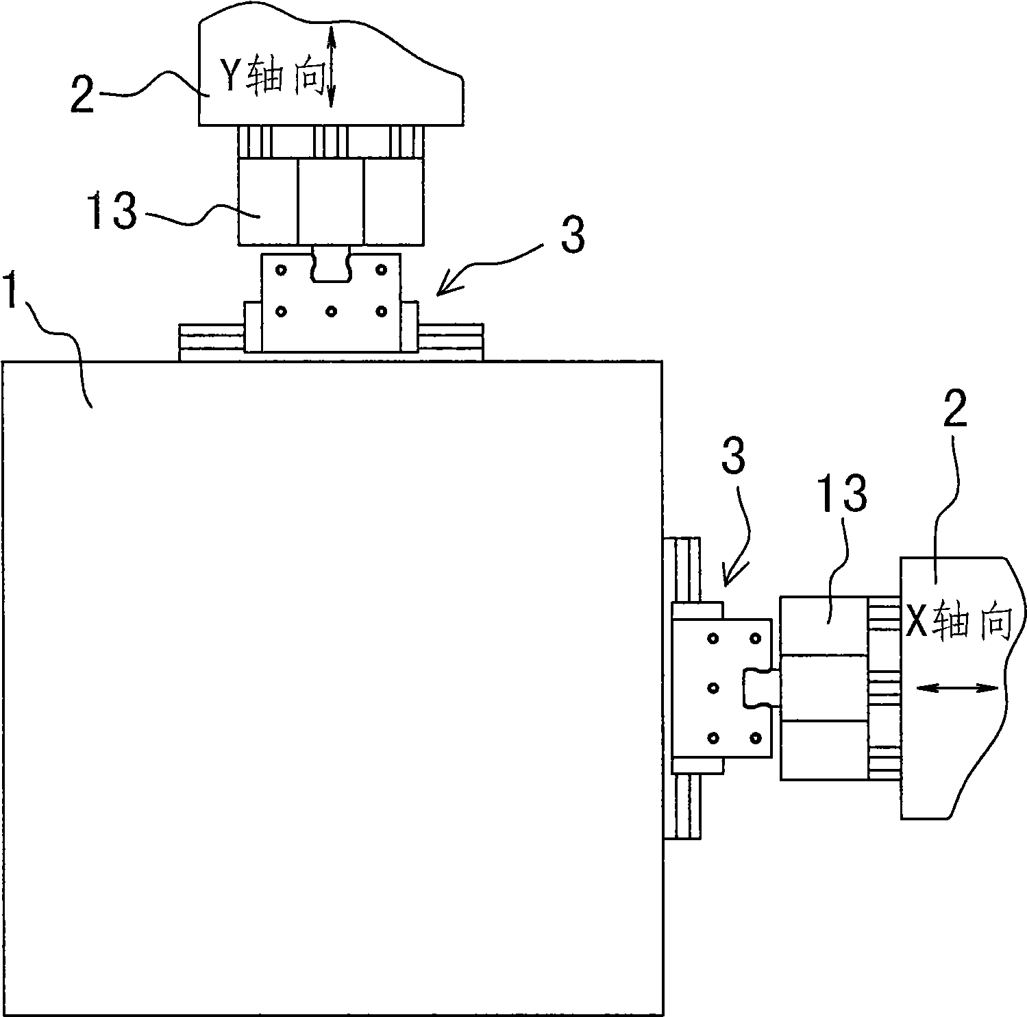
[0041] Embodiment one: see attached Figure 4~5 As shown, a three-axis vibration composite test device has a working table 20, and the working table 20 is connected to the Z-axis vibration generator 21 through the first axial vibration transmission mechanism 24 in the vertical Z-axis, and the horizontal The X-axis is connected to the X-axis vibration generator 22 via the second axial vibration transmission mechanism 25 , and the Y-axis vibration generator 23 is connected to the horizontal Y-axis via the third axial vibration transmission mechanism 26 .

[0042] The first axial vibration transmission mechanism 24 includes upper and lower splints 27, 28 and a central panel 29. A connecting body 41 is arranged under the working surface 20. The cross section of the connecting body 41 is "H-shaped", and the top end of the circumferential wall is It is fixedly connected with the bottom surface of the work surface 20, and its central transverse plate body is the central panel 29, and...

Embodiment 2

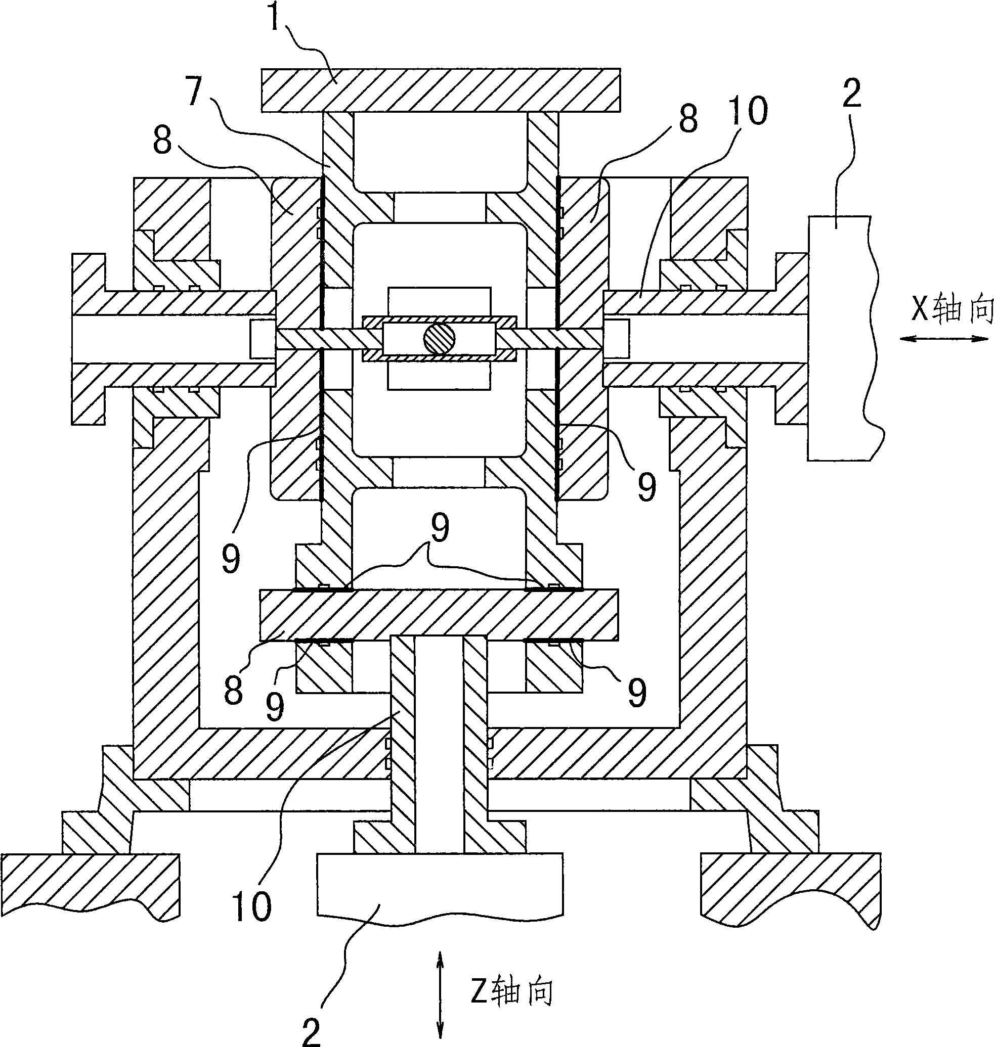
[0047] Embodiment two: see attached Figure 6~7 As shown, a triaxial vibration compound test device has a working table 20, and the difference from Embodiment 1 is that there is no connecting body 41, and the upper surface of the upper splint 27 is directly used as the working table 20, and the center panel 29 The bottom surface is fixedly connected to the connecting piece 37, and is connected with the vibrating body of the Z axial vibration generator 21 through the connecting piece 37; on the lower clamping plate 28, the avoidance connecting piece 37 has an escape groove 43; the side portion of the upper clamping plate 27 is directly connected to the second The axial vibration transmission mechanism 25 is fixedly connected to the transverse guide rail 32 in the third axial vibration transmission mechanism 26 . An annular dust-proof film 39 is connected between the circumference of the bottom of the upper splint 27 and the top of the Z-axis guide bracket 35 to close the circum...

Embodiment 3

[0048] Embodiment three: see attached Figure 8 As shown, a three-axis vibration composite test device includes a working table 20, three vibration generators and three axial vibration transmission mechanisms; the difference from Embodiment 1 is that the second axial vibration transmission mechanism 25 and the third axial vibration transmission mechanism 26 are cross linear guide rail pairs, and each cross linear guide rail pair respectively includes a transverse guide rail 32, two longitudinal guide rails 33 and two sliders 31, and the two longitudinal guide rails 33 are arranged in parallel, and the transverse guide rails 32 and two longitudinal guide rails 33 are distributed in a cross, and a slide block 31 is respectively set at the two intersection points. Of course, the transverse guide rail 32, the longitudinal guide rail 33 and the slide block 31 are still slidingly connected. The longitudinal guide rails 33 in the two parallel second axial vibration transmission mecha...


PUM


Abstract

A triaxial vibration composite testing device is provided with a worktable, and is characterized in that both a horizontal X-axis second axial transmission-vibration mechanism and a horizontal Y-axis third axial transmission-vibration mechanism are cross linear guide rail pairs, while a first axial transmission-vibration mechanism vertical to Z-axis comprises an upper clamp plate, a lower clamp plate and a central panel, wherein the upper clamp plate and the lower clamp plate are aligned vertically and arranged horizontally, the central panel is positioned between the upper clamp plate and the lower clamp plate, the upper clamp plate and the lower clamp plate oppositely clamp the central panel, the lower surface of the upper clamp plate and the upper surface of the central panel are in clearance fit to form an upper fit plane, the upper surface of the lower clamp plate and the lower surface of the central panel are in clearance fit to form a lower fit plane, and high-pressure oil is pumped into gaps of the upper fit plane and the lower fit plane to form static-pressure oil films so as to form a static-pressure plane bearing mechanism. The invention can further improve performance (working frequency in particular), improve capability of resisting capsizing moment, simplify structure, and lower manufacturing difficulty and cost.

Description

technical field [0001] The invention relates to mechanical environment test equipment, in particular to a X, Y, Z three-axis vibration composite test device. The three-axis vibration compound test device can be used to simulate the vibration environment in which the three axes of X, Y, and Z act independently, and can also be used to simulate the compound vibration environment in which the three axes of X, Y, and Z act simultaneously. Background technique [0002] The natural vibration experienced by the product under actual working conditions is the composite vibration of the X, Y, and Z axes. In order to truly reflect the anti-vibration performance of the product and simulate the natural vibration environment, people have tried to design a three-axis vibration composite test device for many years. [0003] At present, there are many kinds of three-axis vibration composite test devices at home and abroad. The structure of these test devices is as follows: including a worki...

Claims


Application Information

Patent Timeline
Patent Type & Authority Applications(China)
IPC IPC(8): G01M7/06
CPCG01M7/06
Inventor 武元桢钟琼华
Owner SUZHOU SUSHI TESTING INSTR CO LTD
Why Eureka
Try Eureka