Mirror-image stereo camera apparatus and method

A stereoscopic camera and equipment technology, applied in the field of image processing, can solve the problems that can not be satisfied at the same time, can not solve the long-distance and short-distance measurement, and the configuration scheme cannot be assembled with the front or top of the vehicle, so as to achieve the effect of extending the baseline length

Inactive Publication Date: 2009-07-22
宁波舜宇智行传感技术有限公司
View PDF0 Cites 20 Cited by
  • Summary
  • Abstract
  • Description
  • Claims
  • Application Information

AI Technical Summary

Problems solved by technology

[0009] In prior art 1, due to installation requirements, the camera focal length and baseline length of the vehicle-mounted binocular stereo camera are fixed, that is, the relationship between the parallax and the distance Z in the three-dimensional space is fixed, so it is impossible to simultaneously perform distance measurement ( Such as vehicle detection 100 to 200 meters ahead during high-speed driving) and short-range detection

Method used


Image

  • Mirror-image stereo camera apparatus and method
  • Mirror-image stereo camera apparatus and method
  • Mirror-image stereo camera apparatus and method

Examples


Embodiment 1

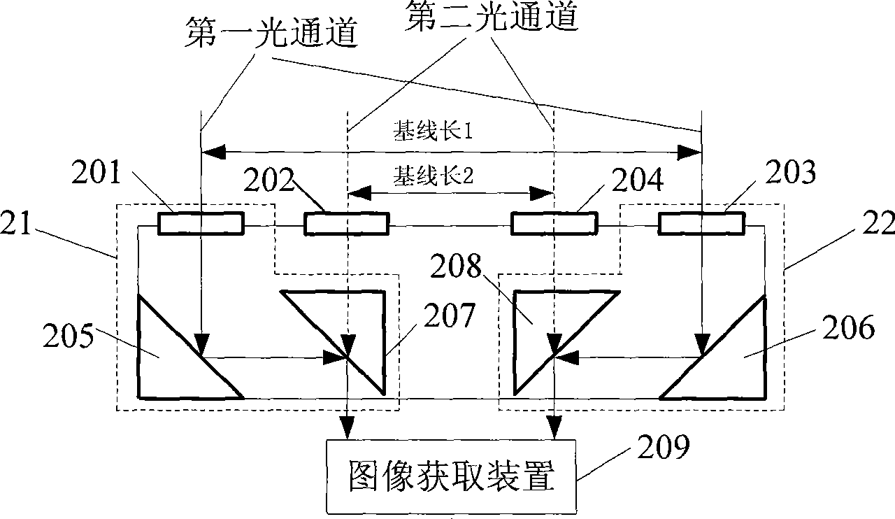
[0057] see figure 2 , the embodiment of the present invention provides a kind of mirror stereo camera equipment, and this equipment comprises:

[0058] Left second lens 202, right second lens 204, at least one left reflection module 21, at least one right reflection module 22 and image acquisition device 209; Left reflection module 21 comprises: left first lens 201, left mirror 205 and left triangular prism 207; the right reflection module 22 includes: the first right lens 203, the right mirror 206 and the right triangular prism 208;

[0059] The left first lens 201 and the right first lens 203 are at a preset distance apart, the left second lens 202 and the right second lens 204 are at a preset distance apart, the left mirror 205 is positioned below the left first lens 201, and the right mirror 206 is positioned at the right Below the first lens 203, the left triangular prism 207 is located below the left second lens 202, and the right triangular prism 208 is located below ...

Embodiment 2

[0099] see Figure 7 , the embodiment of the present invention provides a mirror stereo camera method using the mirror stereo camera device provided in Embodiment 1, the method comprising:

[0100] 701: The incident light enters from the left first lens, and enters the image acquisition device after being reflected by the left mirror and the left triangular prism; the incident light enters from the left second lens, and enters the image acquisition device through the left triangular prism;

[0101] Wherein, the first lens and the second lens adopt structures that transmit different wavelengths;

[0102] For example, the first lens and the second lens adopt coating structures with different wavelengths; the first lens can be a red lens with a transmission wavelength above 700nm, and the second lens can be a green lens with a transmission wavelength below 540nm.

[0103] 702: Simultaneously with 701, the incident light enters from the first right lens, and enters the image acqu...


PUM


Abstract

The embodiment of the invention discloses mirror image stereo videography equipment and a method thereof, belonging to the field of image processing. The method comprises the steps as follows: an incoming ray enters from a first left lens into an image acquisition device after being reflected by a left reflecting mirror and a left triple prism; the incoming ray enters from a second left lens into the image acquisition device through the left triple prism; at the same time, the incoming ray enters from a first right lens into the image acquisition device after being reflected by a right reflecting mirror and a right triple prism; the image acquisition device carries out processing on the collected incoming ray to obtain the distance of the three-dimensional space. The equipment comprises: a second left/right lens, at least a left reflecting module, at least a right reflecting module and the image acquisition device. The embodiment of the invention can simultaneously measure long distance and short distance.

Description

technical field [0001] The invention relates to the field of image processing, in particular to a mirror image stereo camera device and method. Background technique [0002] In today's society, cars have become an indispensable means of transportation. While people are enjoying the convenience and speed brought by automobiles, automobile traffic accidents have become an increasingly severe global social problem. The on-board environment perception system uses various sensors to detect information such as the vehicle itself, the surrounding environment, and the driver's state. By comparing with preset standards, it can judge whether the vehicle is in a dangerous state and the degree of danger. etc. to warn the driver. [0003] In the prior art, the camera system for vehicle-mounted stereo environment perception mainly uses a binocular stereo camera to measure information such as three-dimensional space coordinates and obstacle positions. The most simple and commonly used b...

Claims


Application Information

Patent Timeline
IPC IPC(8): G03B35/08
Inventor 欧阳骏胡振程叶建军汪林田臣礼沈华东张旭高晓平
Owner 宁波舜宇智行传感技术有限公司
Why Eureka
Try Eureka