Composite fractal antenna comprising two fractals

A fractal antenna and fractal technology, applied in antennas, radiating elements, electrical components, etc., can solve problems such as not being the best solution for improving antenna performance, increasing mutual coupling and radiation loss, and reducing substrate dielectric constant , to achieve the effect of multi-current effective path length, lower resonance frequency, and miniaturization

Inactive Publication Date: 2009-07-22
EAST CHINA NORMAL UNIV
View PDF0 Cites 23 Cited by
  • Summary
  • Abstract
  • Description
  • Claims
  • Application Information

AI Technical Summary

Problems solved by technology

Reducing the dielectric constant of the substrate, or even removing the substrate at the key part of the antenna, and making the medium in this place air can suppress surface waves and improve bandwidth, but the width of the feeder will increase accordingly, increasing In order to avoid mutual coupling and radiation loss with the radiating unit, these situations need to be avoided
Therefore, these traditional methods are not the best solution to improve the performance of the antenna

Method used


Image

  • Composite fractal antenna comprising two fractals
  • Composite fractal antenna comprising two fractals
  • Composite fractal antenna comprising two fractals

Examples


Embodiment 1

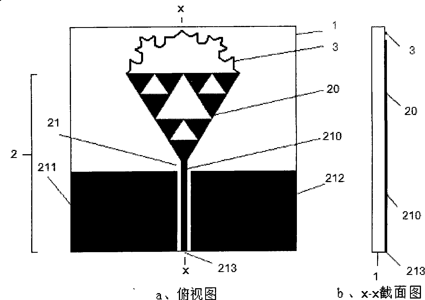
[0020] The structure of embodiment one embodiment, see figure 1 .

[0021] The present embodiment is a planar composite fractal antenna, the dielectric substrate 1 is a radio frequency plate, and the fractal feed unit 20 is a second-order Sierpinski fractal unit, that is, a regular triangle of a first-order Sierpinski fractal and three second-order Sierpinski fractals are hollowed out. The 0-order Sierpinski fractal of the triangle, the shape of the 0-order Sierpinski fractal is an equilateral triangle, and the second fractal 3 is the second-order Koch fractal ring, which is composed of the second-order Koch fractal curve segment, the first-order Koch fractal curve segment and the 0-order Koch fractal curve segment The synthetic curvilinear narrow strip, a vertex of the 0-order Sierpinski fractal is integrated with the upper end of the central signal line 210, and the second-order Koch fractal ring is electrically connected with the other two vertexes of the 0-order Sierpinski...

Embodiment 2

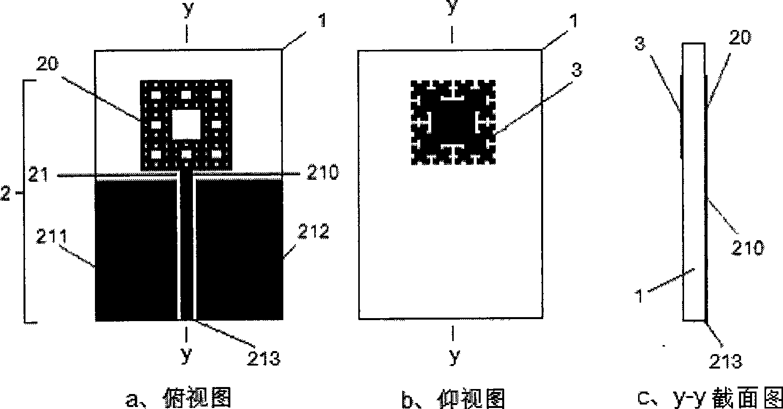
[0033] Embodiment Two The structure of this embodiment, see figure 2 .

[0034]The present embodiment is a three-dimensional composite fractal antenna, and the fractal feeding unit 20 is a third-order Sierpinski carpet, and the shape of the third-order Sierpinski carpet is a square, and the central part of one side of the third-order Sierpinski carpet is integrated with the upper end of the central signal line 210, The second fractal 3 is a third-order RFC fractal unit. The third-order RFC fractal unit is attached to the lower surface of the dielectric substrate 1 in such a way that its square covers the third-order Sierpinski carpet. The microwave transmission line 21 is a coplanar waveguide feeder.

[0035] The main technical data of this embodiment are listed below:

[0036] The dielectric substrate 1 is a FR4 glass fiber plate, and its length, width, thickness, dielectric constant and loss tangent are 36mm, 24mm, 1.0mm, 4.4 and 0.02 respectively;

[0037] The shape of t...


PUM


Abstract

A compound antenna containing two fractals belongs to the technical field of multiband small size antenna. On the basis of the traditional fractal antenna, an antenna fractal is added, the two fractal antennae form the compound antenna; wherein one fractal construction unit is taken as a feeding unit of the whole antenna; when the feeding unit obtains electromagnetic wave energy from a feed source by a feeder line, coupling current can be generated on the fractal parasitized or connected with the other fractal antenna; when the coupling current and current on the feeding unit are in the same flow direction and the same phase position, the two currents in the same flow direction lead the distant field radiation to be superimposed in phase, thus improving the radiation characteristic of the antenna, achieving the impedance matching in the frequency band near the resonance point and expanding the frequency bandwidth. The applicable frequency range of the compound fractal antenna is from UHF frequency band of hundreds of MHz to millimeter wave frequency band of dozens of GHz.

Description

technical field [0001] The invention relates to a composite fractal antenna containing two types of fractals, in particular to a planar or three-dimensional composite fractal antenna composed of two different fractal structures, and belongs to the technical field of multi-band small antennas. Background technique [0002] With the rapid development of wireless communication technology, people continue to put forward new requirements for antennas, such as miniaturization and multi-band. For this reason, the concept of fractal can be introduced into the antenna structure to meet this requirement. Fractal has the ability of space self-filling and self-similar properties. When the concept of fractal is introduced into the antenna structure, a fractal antenna is obtained. Fractal antennas have the characteristics of miniaturization and multi-frequency, so they are especially suitable for broadband and ultra-wideband communication fields. At present, the research on single fract...

Claims


Application Information

Patent Timeline
Patent Type & Authority Applications(China)
IPC IPC(8): H01Q1/38H01Q13/08
Inventor 张顺波朱守正廖斌肖光国王小玲
Owner EAST CHINA NORMAL UNIV
Why Eureka
Try Eureka