Piezoelectric pump

A piezoelectric pump and piezoelectric element technology, applied in the field of piezoelectric pumps, can solve the problems of inability to increase discharge pressure, drop in discharge pressure, and inability to discharge fluid reliably, and achieve simple structure, high discharge pressure, and good tracking Effect

Active Publication Date: 2009-07-22
MURATA MFG CO LTD
View PDF3 Cites 18 Cited by
  • Summary
  • Abstract
  • Description
  • Claims
  • Application Information

AI Technical Summary

Problems solved by technology

However, since only the central portion of the diaphragm is displaced at the portion facing the first opening of the diaphragm, the peripheral portion (cushion portion) of the diaphragm is bent and deformed later than the displacement, so it is necessary to use a soft material. As a diaphragm, the discharge pressure cannot be increased
For example, when the fluid is a compressive fluid such as air, a very soft material such as rubber or resin must be used to elastically deform the cushioning part of the diaphragm, and the discharge pressure drops.
As a result, the fluid may not be reliably discharged under conditions where the pressure outside the pump chamber is high.

Method used


Image

  • Piezoelectric pump
  • Piezoelectric pump
  • Piezoelectric pump

Examples


Embodiment 1

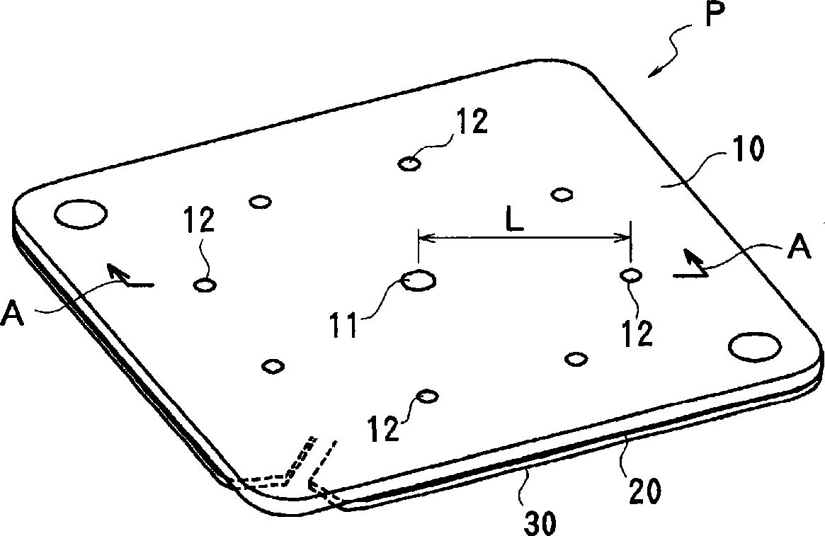
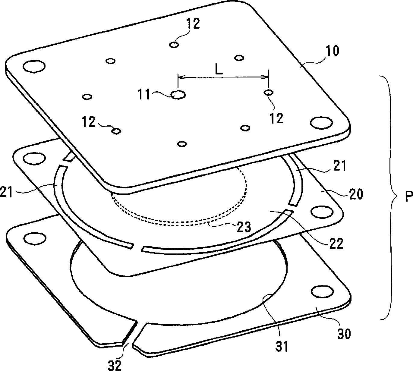
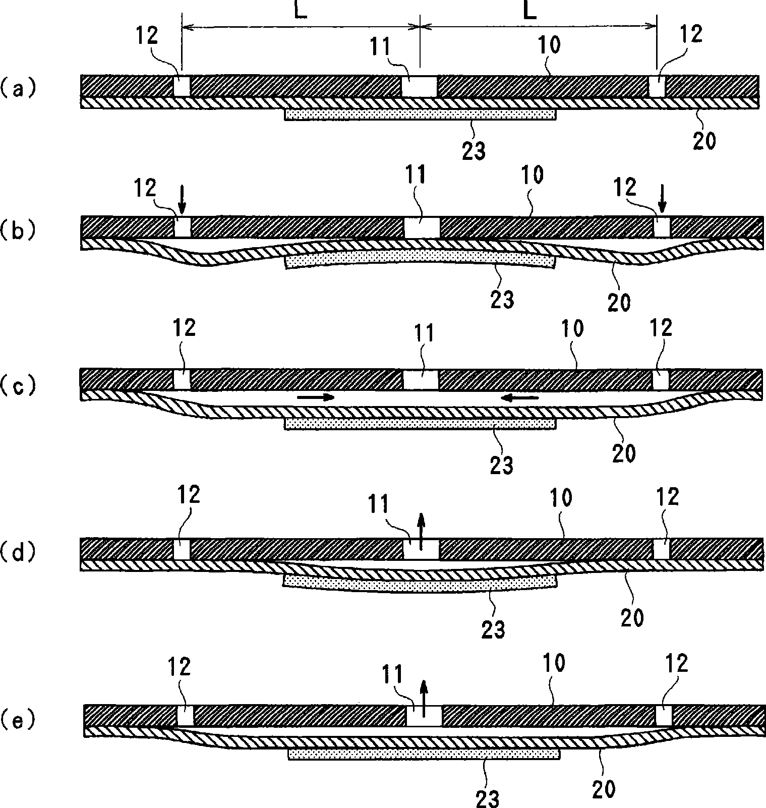
[0037] Figure 1 ~ Figure 3 A first embodiment of a piezoelectric pump is shown. here, figure 1 is an overall perspective view of the piezoelectric pump according to the present invention, figure 2 yes figure 1 An exploded perspective view of the piezoelectric pump shown, image 3 yes figure 1 Sectional view of line A-A.

[0038] The structure of the piezoelectric pump P of this embodiment is that the top plate 10 constituting the pump body, the diaphragm 20, and the ring-shaped pressing plate 30 are stacked in sequence, and these parts are stacked and bonded. The top plate 10 is formed in a rigid flat plate shape, a first opening 11 is formed at the center thereof, and a plurality of second openings 12 are formed on the same circumference around the first opening 11 . Here, eight second openings 12 are formed to ensure the flow rate, but the number of second openings 12 can be set arbitrarily according to the required flow rate.

[0039] The diaphragm 20 is formed of ...

Embodiment 2

[0055] Figure 5 The pump action operation in the third resonance mode of the second embodiment of the present invention is shown. For with image 3 The same parts are marked with the same reference numerals, and repeated explanations are omitted. In the first embodiment, the second opening 12 is provided on the pump body 10 , but in this embodiment, the second opening 25 is provided on the diaphragm 20 . At this time, if driven in the tertiary resonance mode, the fluid can be sucked from the second opening 25 on the back side of the piezoelectric pump and discharged from the first opening 11 on the front side. This structure is ideal as an air supply pump or a cooling pump for the fuel cell.

Embodiment 3

[0057] Figure 6 The pump action operation in the third resonance mode of the third embodiment of the present invention is shown. For with image 3 The same parts are marked with the same reference numerals, and repeated explanations are omitted. In this embodiment, a part of the pump body 10 is extended outward from the diaphragm 20 , and a groove-shaped second opening 16 extending from the inner side to the outer side of the outer peripheral portion of the diaphragm 20 is formed on the lower surface side of the extended portion 15 . The inner end of the second opening 16 is located outside the outer periphery of the piezoelectric element 23 and inner than the outer periphery fixing portion of the diaphragm 20 , and the outer end is opened from the extension portion 15 to the lower surface side. In addition, the second opening 16 does not have to be in the shape of a groove, but may be formed as an inner end opening on the outside of the piezoelectric element 23 and inside ...


PUM


Abstract

The invention provides a piezoelectric pump having a simple structure and high discharge pressure. A first opening (11) is formed at the center of a pump body (10), and a second opening (12) is formed at a position away from the center. The outer periphery of a metal diaphragm (20) is fixed to the pump body (10), and a piezoelectric element (23) is bonded to the center on the rear side of the diaphragm (20). The piezoelectric element (23) has a size covering the first opening (11) but not reaching the second opening (12). When a voltage near the resonance frequency is applied to the piezoelectric element (23), that portion of the diaphragm (20) that faces the first opening (11) and that portion of the diaphragm (20) that faces the second opening (12) are bent and deformed in the directions opposite to each other. This causes fluid to be drawn from either one of the first opening (11) and the second opening (12) and discharged from the other. The piezoelectric pump can have high discharge pressure, which enables the pump to reliably discharge fluid even in conditions where the pressure on the discharge side is high.

Description

technical field [0001] The present invention relates to a piezoelectric pump, and more particularly, to a piezoelectric pump using a diaphragm deformed by a piezoelectric element. Background technique [0002] Piezoelectric pumps can be used for cooling pumps for small electronic devices such as notebook computers, or for pumping fuel for fuel cells. A piezoelectric pump is a pump using a diaphragm that bends and deforms when a voltage is applied to a piezoelectric element, and has the advantages of a simple structure, thinness, and low power consumption. In the case of a piezoelectric pump using a piezoelectric element as a driving source, check valves are provided at the inlet and outlet, and the reliability of the check valve may decrease due to long-term use, or foreign matter such as dust may adhere to the check valve. Rather than the problem of insufficient fluid delivery. In addition, when the piezoelectric element is driven at a high frequency due to foreign substa...

Claims


Application Information

Patent Timeline
Patent Type & Authority Applications(China)
IPC IPC(8): F04B43/04F04B45/04F04B45/047
CPCF04B45/04F04B43/04F04B43/046Y02E60/50F04B2201/0806F05B2280/10F05B2260/407F05B2210/11F04B45/047F04B45/045F04B43/028F05B2260/60Y10S417/00
Inventor 神谷岳须永绿
Owner MURATA MFG CO LTD
Why Eureka
Try Eureka