Low-resistance anti-block vertical flow wetland structure

An anti-clogging and unified technology, applied in the direction of sustainable biological treatment, water/sludge/sewage treatment, biological water/sewage treatment, etc., can solve the problems of easy clogging, high water resistance, difficult to clean, etc., to prevent clogging , water distribution evenly, the effect of saving land

Inactive Publication Date: 2009-07-29
NANJING INST OF GEOGRAPHY & LIMNOLOGY
View PDF0 Cites 11 Cited by
  • Summary
  • Abstract
  • Description
  • Claims
  • Application Information

AI Technical Summary

Problems solved by technology

[0003] The object of the present invention is to develop a new vertical flow wetland structure for the technical problems of high water flow resistance, easy blockage, and difficult cleaning in the vertical flow wetland, so as to minimize the running resistance and driving water level difference of the water distribution and water collection system, Realize the automatic cleaning of the water distribution system and the forced cleaning of the filling matrix to achieve the purpose of lasting and stable operation

Method used


Image

  • Low-resistance anti-block vertical flow wetland structure
  • Low-resistance anti-block vertical flow wetland structure
  • Low-resistance anti-block vertical flow wetland structure

Examples


Embodiment Construction

[0033] The present invention carries out engineering application according to the following steps:

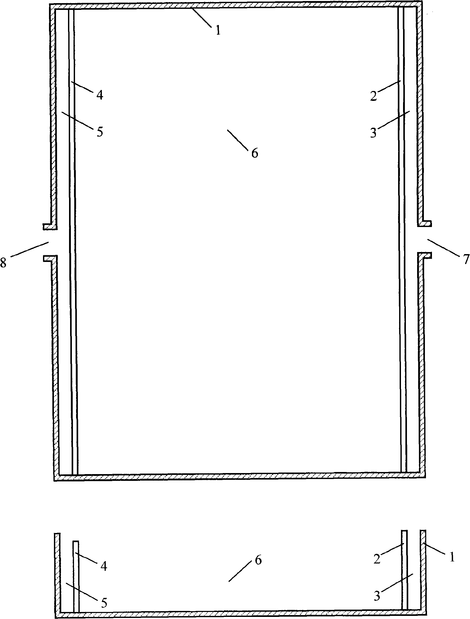
[0034] (1) According to the flow requirements and geological conditions, design and build a hard pool body, and cut a "V"-shaped weir on the top of the ditches separating the pools.

[0035] (2) Fill the gravel cushion in the filler tank to the height where the water distribution pipe is installed.

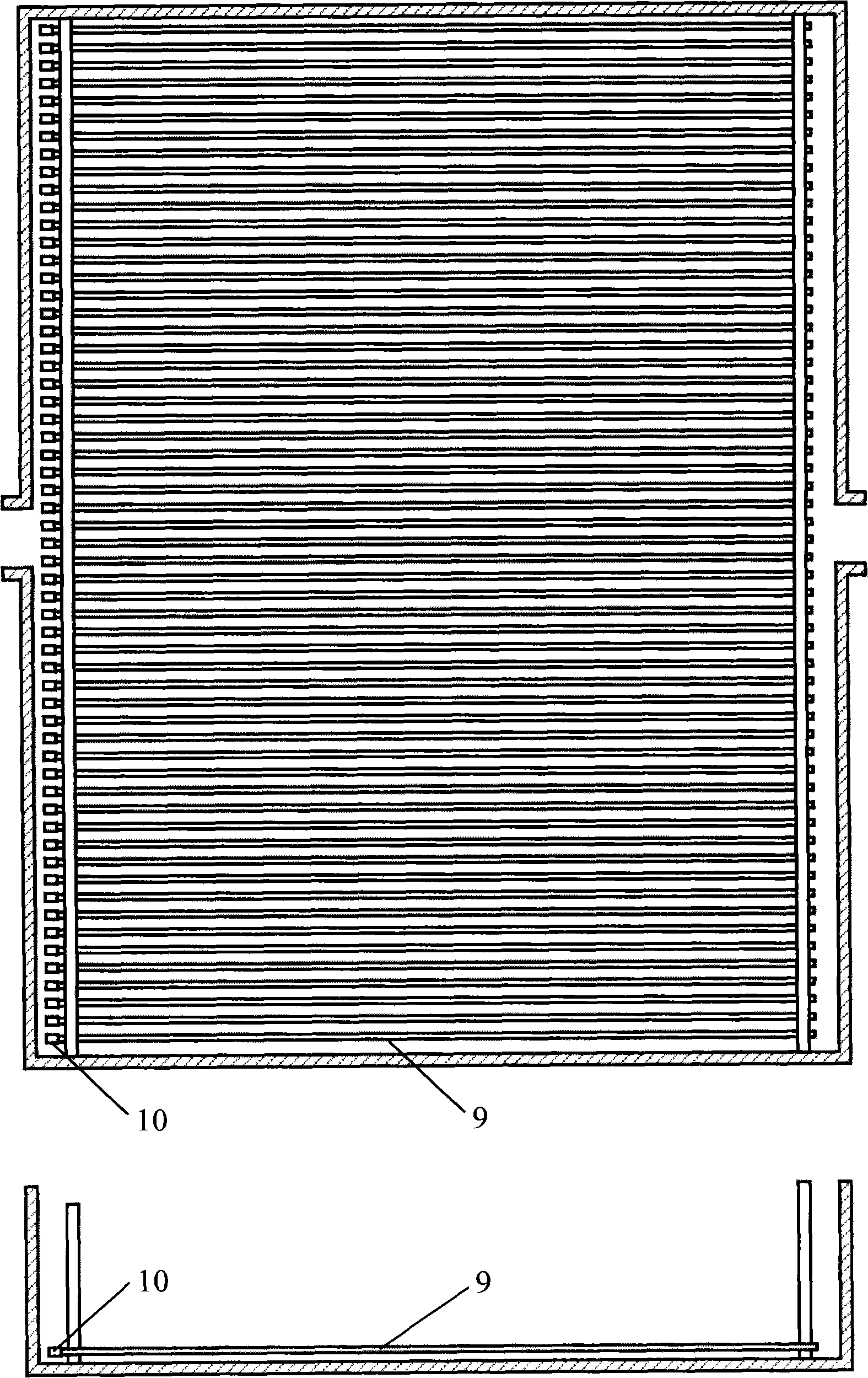
[0036] (3) Drill holes at a specific height on the ridge of the separation pool, install water distribution pipes, and build a protective cover with dry bricks.

[0037] (4) Fill the filler pool with gravel (or other fillers) to a height of 100-150 mm below the bottom of the "V"-shaped weir.

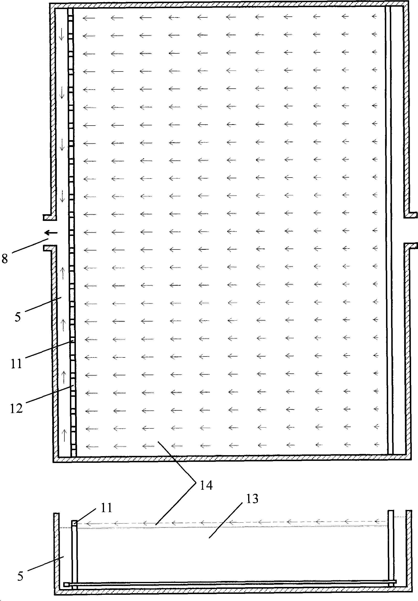
[0038] (5) Inject water into the distribution ditch and the water collection ditch at the same time to the height of the bottom of the "V" shaped weir.

[0039] (6) Plant hygrophytes in the filling pond, maintain the water level and maintain and manage them until they survive.

[0040] (7)...


PUM

PropertyMeasurementUnit
depthaaaaaaaaaa
thicknessaaaaaaaaaa

Abstract

The invention relates to a low-resistance anti-blockage vertical flow wetland structure. A rectangular pressure-bearing pool (20 to 30 meters deep and unlimited in length and depth) is parallelly divided into a water distribution ditch, a filling basin and a water collecting ditch by two separating pool ridges, wherein the separating pool ridge between the filling basin and the water collecting ditch is 300 millimeters lower than the other poll ridge and is uniformly distributed with 'V'-shaped weirs on the top, and the water distribution ditch and the water collecting ditch are communicated with adjacent process units through a water inlet and a water outlet; water distribution pipes are parallelly arranged at the bottom of the filling basin at 500 millimeter intervals on a plane at a height of 30 millimeters, the water inlet ends of the water distribution pipes pass through one separating pool ridge to be exposed in the water distribution ditch, the other ends of the water distribution pipes pass through the other separating pool ridge to be exposed in the water collecting ditch and are blocked by plugs with threaded-openings, and the water distribution pipes are provided with dense water outlet holes and are protected by a dry brickwork outer shell; a filling is filled in the filling basin to a level 100 to 150 millimeters lower than the 'V'-shaped wires, water is filled into the filling basin, plants are planted in the filling basin and the filling basin is put into operation; and water flow from the prior process unit first enters the water distribution ditch through the water inlet, then enters the water distribution pipes from the water distribution ditch, later on overcomes the resistance of the water outlet holes on the water distribution pipes to enter a filling layer, rises slowly at a constant and low speed from the filling layer to a free water layer above the filling layer, overflows from the 'V'-shaped wires and falls into the water collection ditch.

Description

Technical field: [0001] Environmental Engineering Technology. The invention relates to a low-resistance anti-clogging vertical flow wetland structure, which is suitable for deep purification of domestic sewage or high-standard purification of lightly polluted surface water, and should be used in combination with other water purification technologies. Background technique: [0002] Vertical flow wetland is a commonly used water purification unit technology, which mainly uses the precipitation, adsorption, microorganisms, wetland plants and their rhizosphere microorganisms on the surface of the filled substrate to achieve water purification. The depth of the vertical flow wetland is relatively large, so the space utilization rate is relatively high. In the combined process, it is usually arranged in the later stage to realize the process of deep clarification of water quality and anaerobic purification (denitrification, etc.). The water distribution and water collection syste...

Claims


Application Information

Patent Timeline
Patent Type & Authority Applications(China)
IPC IPC(8): C02F3/32C02F3/34
CPCY02W10/10
Inventor 李文朝冯慕华潘继征
Owner NANJING INST OF GEOGRAPHY & LIMNOLOGY
Why Eureka
Try Eureka