
Frequency signal generating method and circuit based on CAN bus

A CAN bus and signal generation circuit technology, applied in the field of locomotive microcomputer control system testing devices, can solve the problems of inability to realize closed-loop control, non-conformance, and fewer output channels, improve testing level and efficiency, avoid large errors, and facilitate The effect of functional expansion

Active Publication Date: 2009-07-29
ZHUZHOU CSR TIMES ELECTRIC CO LTD
View PDF0 Cites 6 Cited by
  • Summary
  • Abstract
  • Description
  • Claims
  • Application Information

AI Technical Summary

Problems solved by technology

[0004] The existing frequency signal generation method has the following problems: ① In the link of signal setting, because the analog circuit cannot be used to give an accurate frequency signal reference, the frequency signal can only be given by adjusting the potentiometer through the knob switch; ② The actual generated The frequency signal cannot be compared with the given signal reference, and closed-loop control cannot be realized. It must rely on human measurement and calculation to judge whether it is accurate; ③The frequency signal generated is not accurate and has a large fluctuation range. When the frequency reaches above 3000HZ, it will jump It is relatively large (that is, the frequency of the potentiometer will change a lot); ④The frequency range of the frequency waveform generated in the form of CPU+DA is relatively narrow, which does not meet the requirements; ⑤The cost of generating the frequency waveform in the form of FPGA+DA is high. The number of output channels is relatively small (each frequency needs a DA channel), and it needs to be refreshed regularly, and the algorithm is more complicated

Method used


Image

  • Frequency signal generating method and circuit based on CAN bus
  • Frequency signal generating method and circuit based on CAN bus

Examples


Embodiment Construction

[0022] The present invention will be further described below in conjunction with the accompanying drawings and specific embodiments.

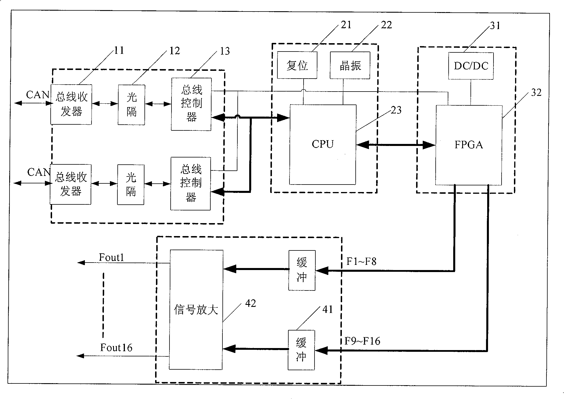
[0023] by attaching figure 1 It can be seen that the present invention is a method for generating a frequency quantity signal based on the CAN bus, and the CAN communication subsystem realizes communication with the upper computer, receives given data of the frequency quantity, and the CAN communication subsystem realizes CAN bus management and sends the received The given frequency data is written into the FPGA on-chip RAM of the FPGA subsystem through the sub-address of the CPU subsystem. The FPGA first converts the given frequency data of the internal RAM into a frequency division coefficient, and then generates a frequency signal in the corresponding channel according to the frequency division coefficient. The level conversion and amplification circuit drives and amplifies the frequency signal generated by the FPGA, and converts the LVCMOS ...


PUM


Abstract

The invention provides a frequency quantity generation circuit based on a CAN bus, consisting of circuits such as a CAN communication sub-system, a CPU sub-system, an FPGA system, a level conversion and an amplification sub-system and the like; the frequency quantity signal generation circuit is arranged on a standard 6U plug-in which can be arranged in a standard 6U case; wherein, the CAN sub-system realizes the communication with a host computer and receives the frequency quantity given data; the CPU sub-system realizes the CAN bus management and writes the received frequency quantity given data into the RAM in the FPGA by address; the FPGA firstly converts the internal RAM frequency quantity given data into a frequency division coefficients, and generates the frequency signals in corresponding passages according to the frequency division coefficient; the level conversion and the amplification sub-system drives and amplifies the frequency signal generated by the FPGA and converts the LVCMOS level into any level frequency waveform signal so as to adapt with different occasions; simultaneously, the CAN sub-system feeds the running states of the CPU sub-system, the FPGA sub-system and the frequency values of all passages back to the host computer, thus facilitating realizing the close loop control.

Description

technical field [0001] The invention belongs to a waveform signal generation method and circuit, in particular to a CAN bus-based locomotive microcomputer control system test device frequency waveform signal generation method and circuit, mainly used for locomotive microcomputer control system test devices. Background technique [0002] One of the functions of the railway locomotive microcomputer control system test bench is to generate various working conditions of the simulated locomotive, and generate various analog, digital, and frequency signals. The frequency is mainly used to simulate the locomotive speed, generator speed, Motor speed, fan speed, diesel engine speed, etc. There are two ways to generate the frequency signal of the test device of the existing locomotive microcomputer control system: one is to use an analog circuit to adjust the potentiometer through the knob switch to generate a corresponding level signal, and then convert the voltage signal into a freq...

Claims


Application Information

Patent Timeline
IPC IPC(8): G05B23/02G06F1/025H03K5/00H03K4/02
Inventor 吴正平周少云何良任湘辉刘智聪
Owner ZHUZHOU CSR TIMES ELECTRIC CO LTD
Learn More