Mold cutter with improved mould-cutting knife structure suitable for reel material

A die-cutting machine and coil technology, which is applied in metal processing and other directions, can solve the problems of long production cycle, high cost of die-cutting tools, and cumbersome machines, so as to reduce production costs, reduce production costs and production requirements, and shorten production. The effect of the production period

Inactive Publication Date: 2009-08-05
杜建刚
View PDF0 Cites 5 Cited by
  • Summary
  • Abstract
  • Description
  • Claims
  • Application Information

AI Technical Summary

Problems solved by technology

The invention is a die-cutting machine with an improved die-cutting tool structure suitable for drum materials, which can solve the high cost of die-cutting tools in the prior art
Long production cycle, poor durability, complicated machine adjustment
heavy machine

Method used


Image

  • Mold cutter with improved mould-cutting knife structure suitable for reel material
  • Mold cutter with improved mould-cutting knife structure suitable for reel material
  • Mold cutter with improved mould-cutting knife structure suitable for reel material

Examples


Embodiment Construction

[0017] The present invention will be described in further detail below in conjunction with the accompanying drawings and specific embodiments.

[0018] The main parts and details of a die-cutting machine suitable for drum materials with improved die-cutting tool structure in the present invention:

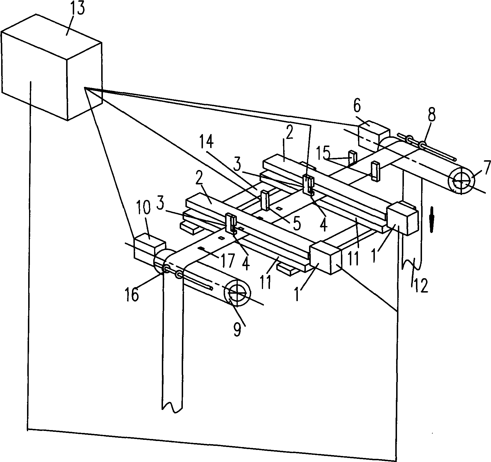
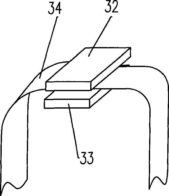
[0019] 1. Knife feeding motor (servo or stepping motor), 2. Horizontal mechanism, 3. Tool holder, 4. Die cutting tool, 5. Mark detection sensor, 6. Traction motor (servo or stepping motor), 7. Traction Roller, 8. Traction roller, 9. Return roller, 10. Return motor, 11. Backing plate, 12. Roll material (die-cut paper), 13. Control system, 14. Knife holder guide rail, 15. Gear Block, 16. Go back and roll, 17. Mark.

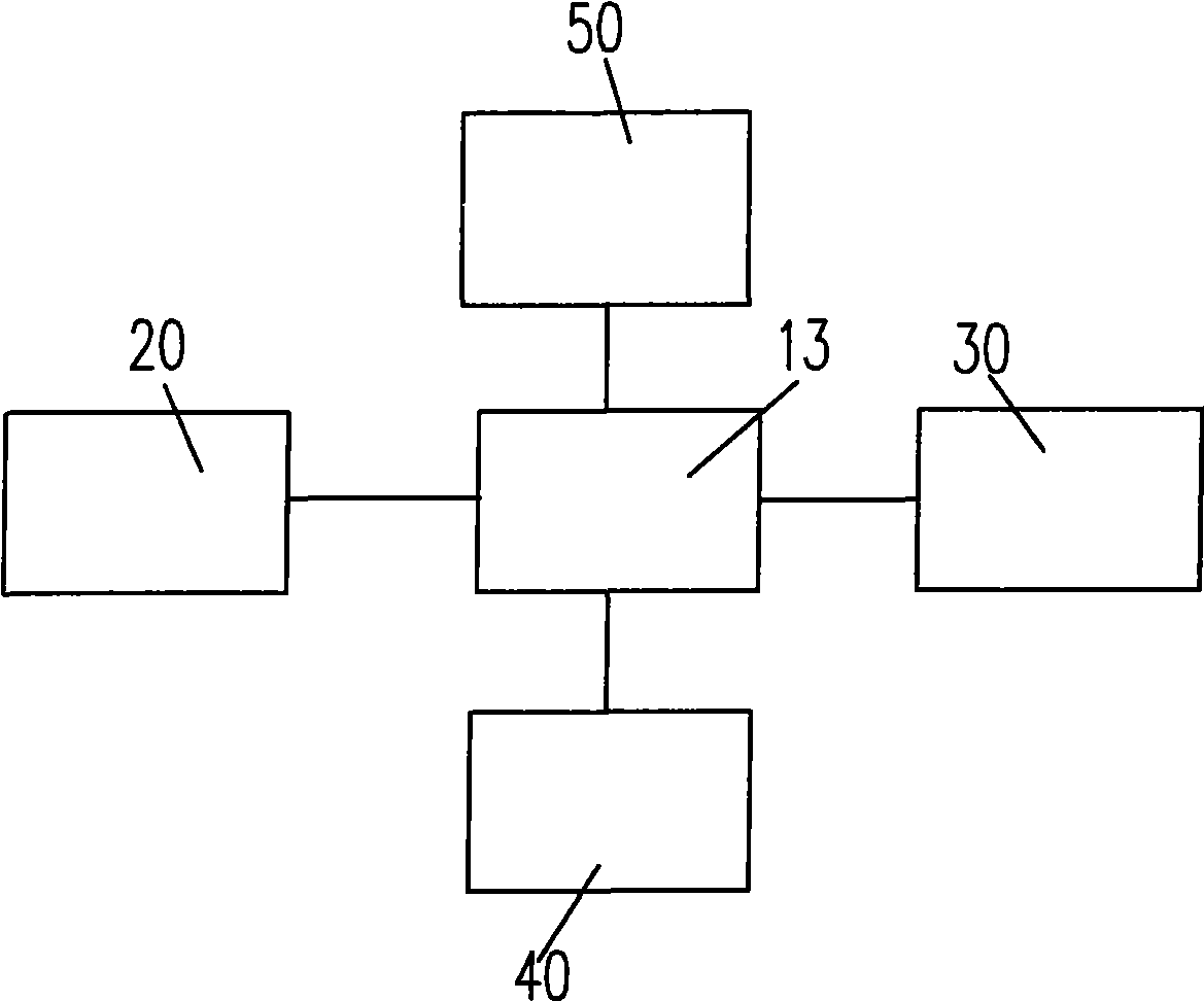
[0020] Such as figure 1 As shown, a die-cutting machine suitable for reel materials with an improved die-cutting tool structure of the present invention mainly includes a control system 13, a frame (not shown in the figure), a coil pulling unit 20, and a coil tensioni...


PUM


Abstract

The invention discloses a die-cutting machine with improved die-cutting tool structure applicable to coiled materials, which can solve the technical problems that die-cutting tools in the prior art are high in cost, long in manufacturing period, poor in durability, complex in machine adjustment, heavy in machine, low in die-cutting quality, low in die-cutting speed, unsuitable for small-batch production, and the like. The die-cutting machine comprises a frame, as well as a coiled-material pulling unit, a coiled-material tensioning device, a mark detecting unit and at least one feed unit which are connected with a control system, wherein the coiled-material pulling unit controls coil material to move forwards along the length direction of the coiled material; the coiled-material tensioning device controls the coiled materials to move reversely along the length direction of the coiled materials; the mark detecting unit comprises marks arranged on the coiled material and a mark detecting sensor; the feed unit controls a die-cutting tool to move along the width direction of the coiled material and controls the die-cutting tool to penetrate or retract relative to the coiled materials; and the feed unit comprises a guide rail arranged along the width direction of the frame, a tool rest which is positioned on the guide rail and connected with a feeding motor, as well as a tool arranged on the tool rest.

Description

technical field [0001] The invention relates to a machine for die-cutting creasing or die-cutting, in particular to a die-cutting machine with an improved structure of a die-cutting tool suitable for drum materials. Background technique [0002] Die-cutting machines are usually used in the manufacturing process of paper or similar material products. Die-cutting machines are divided into flat-pressed flat, circular-pressed round, flat-pressed round or Round flattened die-cut form. At present, the die-cutting forms of flat pressing and round pressing are commonly used in die-cutting machines. Among them, such as Pic 4-1 and Figure 4-2 The structure in the form of flat die-cutting shown includes a die-cutting plate 31 located below the upper platen 32 and a lower backing plate 33 located below the receiving medium 34. The flat-pressed flat die-cutting relies on the downward punching of the die-cutting plate 31 The characteristics of the flat die-cutting are: there are high...

Claims


Application Information

Patent Timeline
IPC IPC(8): B26D5/08B26F1/00
Inventor 杜建刚
Owner 杜建刚
Why Eureka
Try Eureka