
Controller applied for resonance type DC/DC converter

A DC converter and controller technology, which is applied to conversion equipment, control/regulation systems, instruments, etc. with intermediate conversion to AC, can solve the problem of easy deviation from the optimal operating point of the system, increase control complexity, and wide range of changes And other issues

Inactive Publication Date: 2009-08-05
LITE ON TECH CHANG ZHOU CO LTD +1
View PDF0 Cites 7 Cited by
  • Summary
  • Abstract
  • Description
  • Claims
  • Application Information

AI Technical Summary

Problems solved by technology

[0003] However, because the frequency of the switch control signal changes with the output power or output voltage, its range of change is too large, and it is easy to deviate from the optimal operating point of the system, resulting in increased loss; moreover, its inherent high-frequency start-up characteristics also increase control complexity
[0004] It can be seen that the above-mentioned existing resonant DC converter obviously still has inconvenience and defects in structure and use, and needs to be further improved urgently.
In order to solve the above-mentioned problems, the relevant manufacturers have tried their best to find a solution, but for a long time no suitable design has been developed, and the general product has no suitable structure to solve the above-mentioned problems. This is obviously the relevant industry. Urgent problem

Method used


Image

  • Controller applied for resonance type DC/DC converter
  • Controller applied for resonance type DC/DC converter
  • Controller applied for resonance type DC/DC converter

Examples


Embodiment Construction

[0023] In order to further explain the technical means and effects of the present invention to achieve the intended purpose of the invention, in conjunction with the accompanying drawings and preferred embodiments, the controller for the resonant DC / DC converter proposed according to the present invention will be described in detail below. Embodiments, structures, features and effects thereof are described in detail below.

[0024] The aforementioned and other technical contents, features and effects of the present invention will be clearly presented in the following detailed description of preferred embodiments with reference to the drawings. Through the description of the specific implementation mode, when the technical means and functions adopted by the present invention to achieve the predetermined purpose can be obtained a deeper and more specific understanding, but the accompanying drawings are only for reference and description, and are not used to explain the present in...


PUM


Abstract

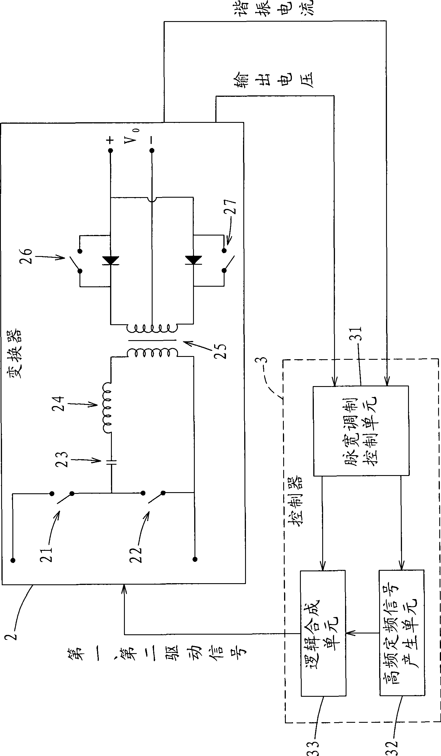
The invention relates to a controller which is applied to a resonance-typed DC / DC converter and used for controlling the shifting switch of the resonance-typed DC / DC converter. The controller comprises a pulse width modulation control unit, a high-frequency and fixed-frequency signal generation unit and a logic synthesis unit; the pulse width modulation control unit detects the output voltage of the resonance-typed DC / DC converter so as to generate a pulse width modulation signal; the high-frequency and fixed-frequency signal generation unit generates a high-frequency and fixed-frequency signal; the logic synthesis unit synthesizes the pulse width modulation signal and the high-frequency and fixed-frequency signal so as to generate a driving signal used for driving all shifting switches; the pulse width modulation control unit also detects the resonance current of the resonance-typed DC / DC converter simultaneously, so as to generate a pulse width modulation signal. The controller combines a first high-frequency and fixed-frequency signal and a second high-frequency and fixed-frequency signal of the fixed frequency with the pulse width modulation signal of the fixed width so as to control all shifting switches, thus ensuring that the resonance-typed DC / DC converter is at the best working point under all load conditions, simplifying the controller structure, reducing the loss of the shifting switch and improving the shifting frequency of the shifting switch.

Description

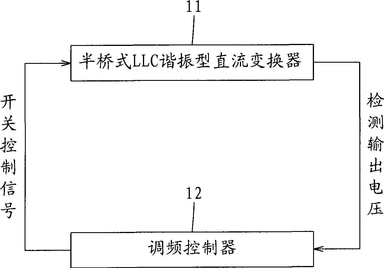
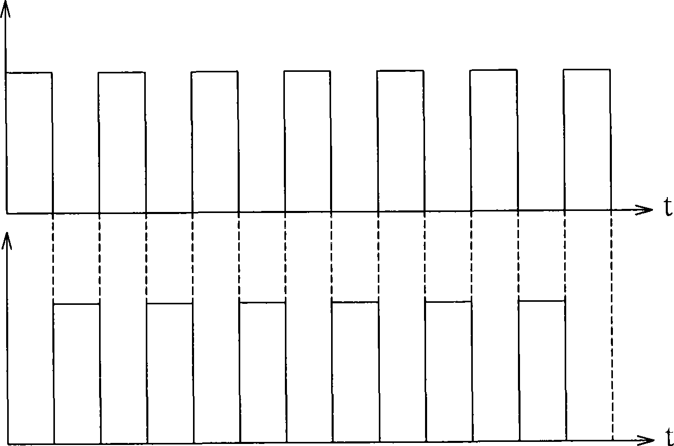
technical field [0001] The present invention relates to a controller, in particular to a controller applied to a resonant DC / DC converter for making the resonant DC converter at the optimum operating point under all load conditions. Background technique [0002] For the example of a half-bridge converter, see figure 1 , figure 2 as shown, figure 1 is a schematic diagram illustrating the main control technology of the existing resonant DC converter, figure 2 It is a schematic diagram illustrating a waveform of an existing switch control signal. At present, the existing half-bridge LLC resonant DC converter 11 is mainly controlled by a frequency modulation controller 12, and the frequency modulation controller 12 detects the half-bridge LLC The output voltage of the resonant DC converter 11 is used to change the frequency of the switch control signal (the signal is the signal, hereinafter referred to as the signal). The waveform of the switch control signal is as follows...

Claims


Application Information

Patent Timeline
Patent Type & Authority Applications(China)
IPC IPC(8): H02M3/28G05F1/46
Inventor 张庆友金晓毅叶志红赵清林冯宇丽
Owner LITE ON TECH CHANG ZHOU CO LTD
Learn More