
Frequency-stabilizing device of fiber-optical grating external cavity semiconductor laser and its frequency-stabilizing method

A fiber grating and laser technology, used in semiconductor lasers, lasers, laser parts and other directions, can solve the problems of changing the laser output frequency, high price, poor mechanical stability, etc., and achieve the effect of improving the signal-to-noise ratio.

Inactive Publication Date: 2003-12-17
TSINGHUA UNIV
View PDF0 Cites 0 Cited by
  • Summary
  • Abstract
  • Description
  • Claims
  • Application Information

AI Technical Summary

Problems solved by technology

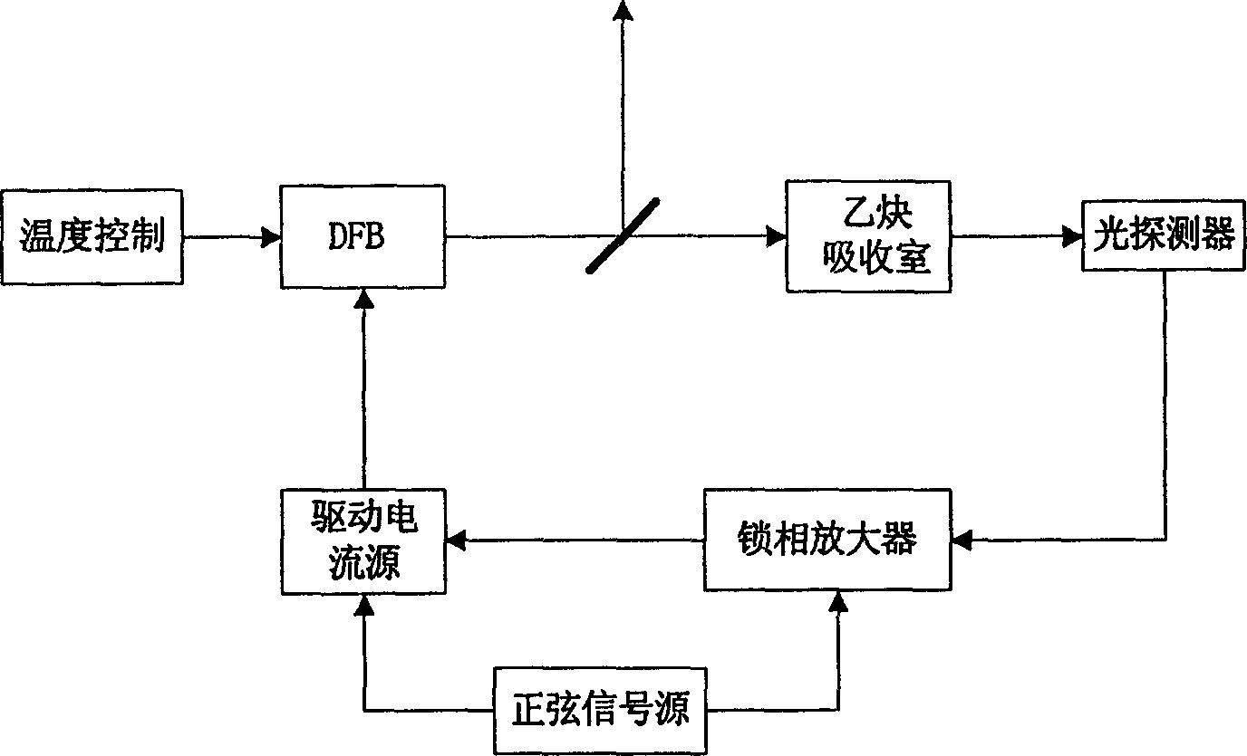
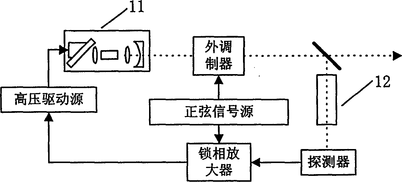
There are only two differences in the frequency stabilization method: (1) The laser frequency control is realized by changing the laser cavity length, and the voltage signal output by the servo feedback controller is applied to the piezoelectric ceramic, thereby changing the cavity length of the external cavity laser , which changes the laser output frequency; (2) The frequency modulation of the laser is realized by an external modulator. This is because the external cavity laser has a long cavity length, so the current frequency modulation effect is not good, and can only be obtained by an external modulator. frequency modulation
The general structure of this kind of volume grating external cavity semiconductor laser includes laser die, lens, mirror and volume grating. The structure is complex, and the mechanical stability is poor, and the price is expensive.

Method used


Image

  • Frequency-stabilizing device of fiber-optical grating external cavity semiconductor laser and its frequency-stabilizing method
  • Frequency-stabilizing device of fiber-optical grating external cavity semiconductor laser and its frequency-stabilizing method
  • Frequency-stabilizing device of fiber-optical grating external cavity semiconductor laser and its frequency-stabilizing method

Examples


Embodiment Construction

[0022] Embodiments of the fiber grating external cavity semiconductor laser frequency stabilization device proposed by the present invention are described in detail in conjunction with the accompanying drawings as follows:

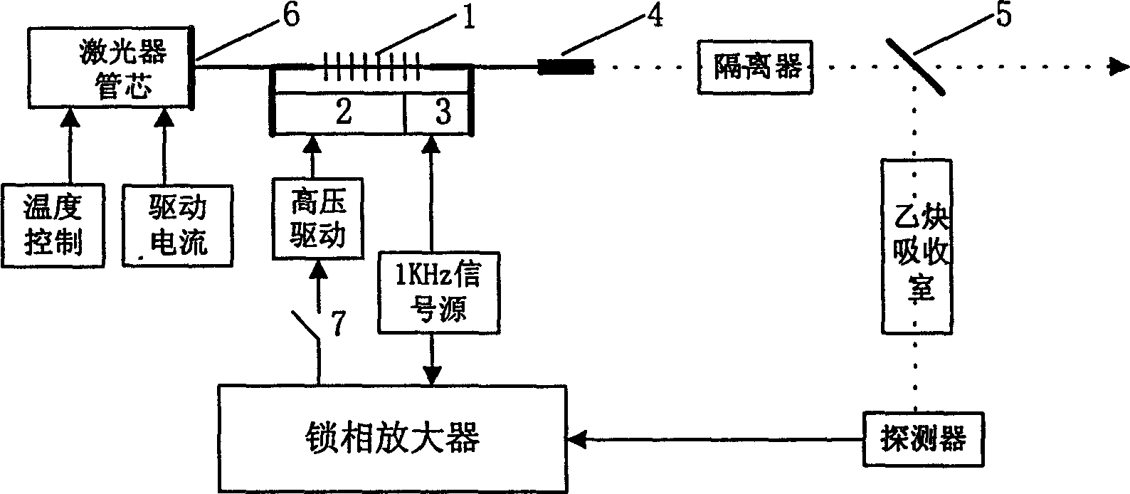
[0023] The overall structure of the device of this embodiment is as follows image 3 As shown, it includes laser light source, acetylene absorption chamber and feedback controller; among them, the laser light source is a fiber grating external cavity semiconductor laser, the laser light source is equipped with a temperature controller, which can achieve a temperature control accuracy of 0.01°C, and the laser current source is a constant current source , These measures ensure the stable output power and frequency of the laser; the acetylene gas absorption chamber is a quartz glass tube with a length of 5 cm and a diameter of 1.5 cm. The tube was filled with 10 Torr of acetylene gas. The feedback controller mainly includes a photodetector, a lock-in amplifi...


PUM


Abstract

The invention relates to a technique field of frequency stabilization of laser light source. It consists of laser source, acetylene gas absorption chamber, and servo-feedback controller. The laser source as a semiconductor laser with optical fiber grating outer cavity is composed of semiconductor laser tube core in quanta trap F-P type and an optical fiber grating. A reflection reducing coating is coated on the coupling end surface of the tube core and optical fiber grating. The other end of the optical fiber grating is linked to a collimator. There are two pieces of piezoelectric ceramics end to end on the two ends of the optical fiber grating. The two input ends of phase locking amplifier in the servo-feedback controller are connected to the output end of light sensor and sine signal source respectively. The one end of the signal source and the high voltage drive are connected to a phase locking amplifier; with the other end connected to said two pieces of piezoelectric ceramics. There is an isolator and a partial reflector located on the optical path between the collimator and the acetylene gas absorption chamber. The invention possesses the advantages of higher stability in frequency, very narrow laser line-width as well as simple structure and higher stability in mechanics.

Description

technical field [0001] The invention belongs to the technical field of frequency stabilization of a laser light source, and in particular relates to a frequency stabilization method using a fiber grating external cavity semiconductor laser. Background technique [0002] Optical wavelength division multiplexing (WDM) system, as one of the main research directions in the current communication field, is developing rapidly. Among many WDM technologies, a highly stable laser light source is one of the key technologies. It is very necessary to achieve dense multiplexing of optical channels, eliminate crosstalk between adjacent channels and improve signal transmission quality. In addition, a high-stability light source is also of great significance to the measurement work in the 1.5μm band. [0003] The principle of frequency stabilization technology is: the light output by the laser is sent to the frequency discriminator for comparison with the reference frequency, and the obtain...

Claims


Application Information

Patent Timeline
Patent Type & Authority Patents(China)
IPC IPC(8): G02F1/00H01S5/068H04J14/00
Inventor 赵华凤薛林张汉一钱进
Owner TSINGHUA UNIV
Learn More