Separator for energy device and energy device having the same

A technology for equipment and energy, which is applied in the field of separators for energy equipment, can solve the problems of energy equipment without obtaining voltage retention rate, and achieve the effect of not being easy to internal short circuit, small aperture, and small unevenness of aperture

Active Publication Date: 2009-08-05
MITSUI CHEM INC
View PDF9 Cites 10 Cited by
  • Summary
  • Abstract
  • Description
  • Claims
  • Application Information

AI Technical Summary

Problems solved by technology

[0005] However, no matter which nonwoven fabric laminate is used, energy devices with sufficient voltage retention have not yet been obtained.

Method used


Image

  • Separator for energy device and energy device having the same
  • Separator for energy device and energy device having the same

Examples


Embodiment 1

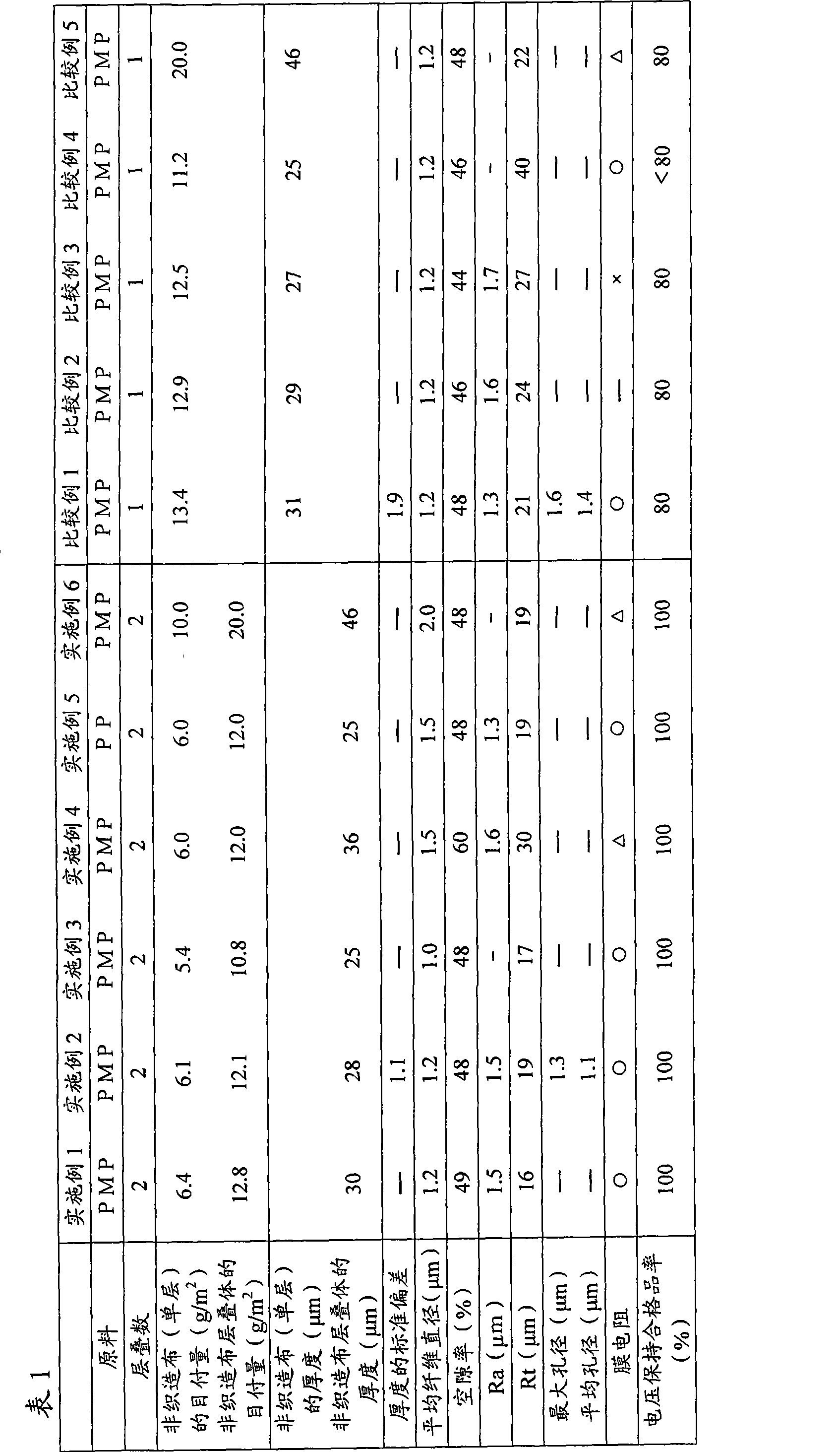
[0104] 4-Methyl-1-pentene copolymer (PMP, trade name: TPX DX820, manufactured by Mitsui Chemicals Co., Ltd., has a melting point of 240° C. and a melt flow rate of 180 g / 10 minutes at 260° C. under a load of 5 kg, The Vicat softening point is 178° C. (ASTM D1525)), melt-spun at a resin temperature of 350° C. by a melt-blowing method, and collected by a web forming machine to obtain a melt-blown nonwoven fabric. The average fiber diameter of the obtained melt-blown nonwoven fabric is 1.2 μm, and the weight per unit is 6.4 g / m 2 .

[0105] Two sheets of the above-mentioned melt-blown nonwoven fabric were prepared, stacked, and compacted with a calender roll (rubber roll and steel roll) set at 160° C. at a linear pressure of 10 kg / cm. The unit weight of the obtained nonwoven fabric laminate was 12.8 g / m 2 , with a thickness of 30 μm and a porosity of 49%. In addition, the Ra value was 1.5 μm, and the Rt value was 16 μm. The film resistance of the sample was good.

[0106] Ne...

Embodiment 2~4 and Embodiment 6

[0110] Using the same 4-methyl-1-pentene copolymer as in Example 1, a melt-blown nonwoven fabric was produced. As shown in Table 1, adjust the unit weight of the melt-blown nonwoven fabric to 5.4-10.0g / m 2 , the average fiber diameter of the melt-blown nonwoven fabric is adjusted to 1.0-2.0 μm.

[0111] Furthermore, using the same apparatus as in Example 1, the pressing force was adjusted, and two melt-blown nonwoven fabrics were laminated to obtain a separator for energy equipment. Table 1 shows the evaluation results of the obtained separators for energy equipment.

Embodiment 5

[0113] A propylene homopolymer (melt flow rate 20 g / 10 minutes, melting point 160° C.) was used instead of the 4-methyl-1-pentene copolymer to produce a melt-blown nonwoven fabric. The evaluation results of the obtained melt-blown nonwoven fabric are shown in Table 1.


PUM

PropertyMeasurementUnit
diameteraaaaaaaaaa
surface roughnessaaaaaaaaaa
diameteraaaaaaaaaa

Abstract

Disclosed is a separator for energy devices, which hardly allows an internal short circuit, while being excellent in electrolyte solution retention. Also disclosed is an energy device comprising such a separator. Specifically disclosed is a separator for energy devices, which comprises a nonwoven fabric laminate composed of two or more melt-blown nonwoven fabric layers arranged on top of one another. Each of the melt-blown nonwoven fabric layers has an average fiber diameter of 0.5-3 [mu]m, and the weight per square meter of the nonwoven fabric laminate is not more than 50 g / m. This separator for energy devices has a surface centerline maximum roughness (Rt value) of not more than 35 [mu]m.

Description

technical field [0001] The present invention relates to a separator for energy equipment including a nonwoven fabric laminate obtained by a meltblown method, and an energy equipment including the same. Background technique [0002] Energy devices such as batteries and electric double-layer capacitors have a basic unit including an electrode pair consisting of a positive electrode and a negative electrode, a separator sandwiched between the electrode pair, and an electrolyte impregnated with the separator. For separators included in energy devices, it is required not only to be able to prevent the short circuit of the positive and negative electrodes, but also to be able to hold the electrolyte so that the electrical reaction can proceed smoothly. Furthermore, separators are required to be thinner in order to realize miniaturization and higher capacity of energy devices. Also, as a separator, a microporous film or a nonwoven fabric is generally used. [0003] As a means to ...

Claims


Application Information

Patent Timeline
Patent Type & Authority Applications(China)
IPC IPC(8): H01M2/16H01G9/02H01M50/403H01M50/454H01M50/489H01M50/491
CPCY02E60/12H01M2/1686B32B5/26H01G9/02H01M10/0525H01M2/145H01G9/155Y02E60/13H01M2/1606B32B5/022B32B2250/20B32B2262/0223B32B2262/023B32B2262/0238B32B2262/0246B32B2262/0253B32B2262/0261B32B2262/0276B32B2262/14B32B2307/20B32B2307/306B32B2307/714B32B2307/73B32B2457/10B32B2457/16Y10T156/10Y10T442/609Y02E60/10H01M50/44H01M50/403H01G11/52H01M50/454H01M50/491H01M50/489H01M50/417
Inventor 须藤康浩岩田匡隆
Owner MITSUI CHEM INC
Why Eureka
Try Eureka