Electric rotating machine

A technology for rotating electrical machines and stator cores, applied in synchronous generators, electromechanical devices, electrical components, etc., can solve problems such as stator coil heat dissipation and stator, and achieve the goal of suppressing poor insulation, suppressing the increase of reluctance, and suppressing temperature rise Effect

Active Publication Date: 2009-08-05
MITSUBISHI ELECTRIC CORP
View PDF2 Cites 4 Cited by
  • Summary
  • Abstract
  • Description
  • Claims
  • Application Information

AI Technical Summary

Problems solved by technology

However, in the prior art described above, no consideration has been given to the technology of effectively dissipating the heat generated by the stator coil to suppress the temperature rise of the stator.

Method used


Image

  • Electric rotating machine
  • Electric rotating machine
  • Electric rotating machine

Examples


Embodiment approach 1

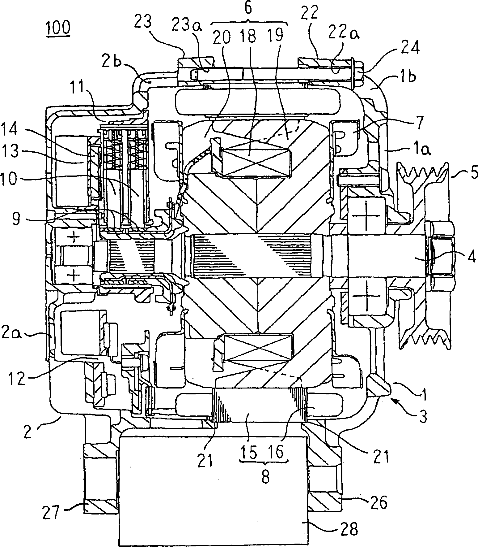
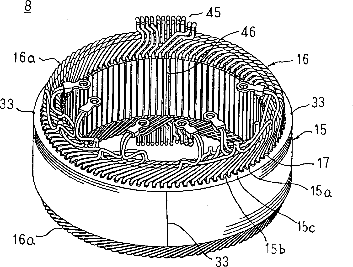
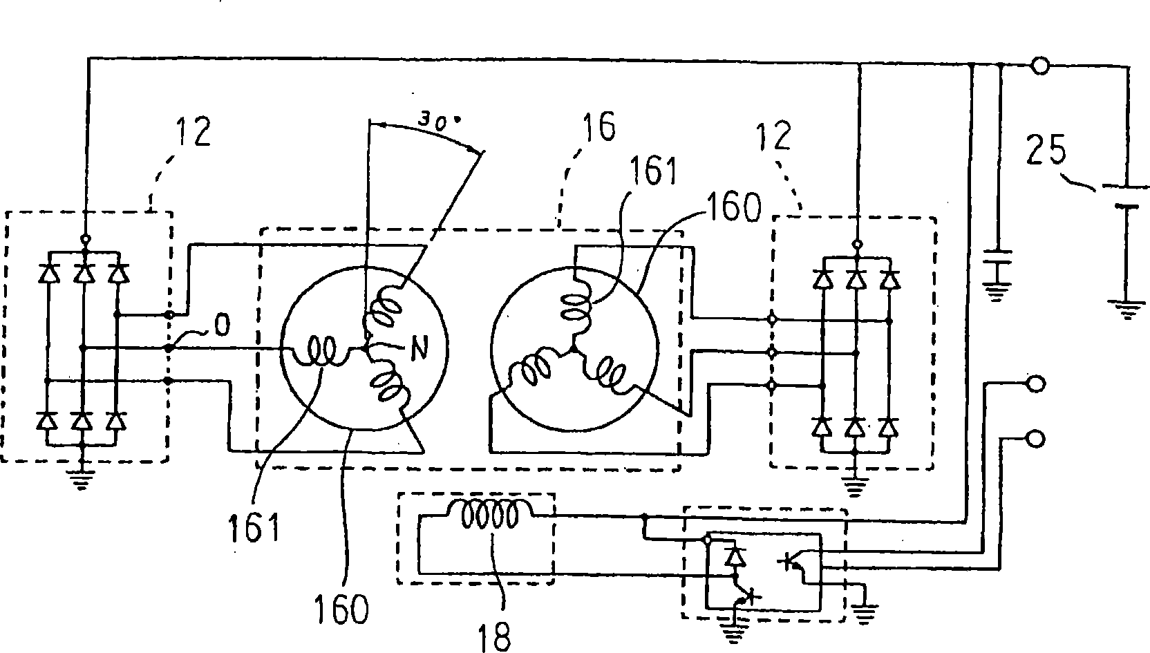
[0028] figure 1 Is a longitudinal cross-sectional view showing a vehicle alternator according to Embodiment 1 of the present invention, figure 2 Is a perspective view showing a stator applied to a vehicle alternator according to Embodiment 1 of the present invention, image 3 Is a circuit diagram showing a vehicle alternator according to Embodiment 1 of the present invention, Figure 4 It is a cross-sectional view of a main part for explaining the fixing structure of the stator of the vehicle AC generator according to the first embodiment of the present invention.

[0029] in Figure 1 to Figure 4 Among them, the vehicle alternator 100 includes a housing 3, which is composed of a front frame 1 and a rear frame 2 that are roughly cup-shaped and made of aluminum as frames; and a shaft rotatably supported on the housing 3 4; a pulley 5 fixed on the end of the shaft 4 extending toward the front side of the housing 3; a rotor 6 fixed on the shaft 4 and housed in the housing 3; fixed...

Embodiment approach 2

[0053] Picture 12 It is a cross-sectional view of a main part for explaining the fixing structure of the stator of the vehicle alternator according to the second embodiment of the present invention.

[0054] in Picture 12 In this case, the insulating film 29 covers the outer peripheral surface of the stator core 15.

[0055] The other structure is the same as that of the first embodiment described above.

[0056] In this second embodiment, similar to the above-mentioned first embodiment, the strip-shaped magnetic thin plates 31 are laminated and integrated to form a rectangular parallelepiped laminated core 32, and the laminated core 32 with the winding assembly 40 is bent into a cylindrical shape. Both ends of the laminated core 34 bent into a cylindrical shape are face-to-face and welded to form the stator core 15. Next, an insulating resin made of, for example, an epoxy resin is applied to the outer circumferential surface of the stator core 15 to form the stator core 15 in ...

Embodiment approach 3

[0061] Figure 13 It is a cross-sectional view of a main part for explaining the fixing structure of the stator of the vehicle alternator according to the third embodiment of the present invention.

[0062] in Figure 13 In the stator core 15A, for example, a strip-shaped magnetic thin plate 31 with a plate thickness (t1) of 0.3 mm is laminated a predetermined number of sheets, and then a strip-shaped magnetic thin plate 31A with a plate thickness (t2) of 1.0 mm is laminated on The two ends of the laminated body of the band-shaped magnetic thin plates 31 are welded into a single body of the laminated body of the band-shaped magnetic thin plates 31 and 31A, then bent into a cylindrical shape, and welded to the abutting portions of the both end surfaces.

[0063] The other structure is the same as that of Embodiment 1 described above.

[0064] In the third embodiment, the strip-shaped magnetic thin plates 31A made of thick plates are arranged at both ends of the laminated body that...


PUM


Abstract

A dynamo-electric machine in which occurrence of poor insulation incident to oxidation of a stator core is suppressed without decreasing the output, and temperature rise of the stator is suppressed by transmitting heat generated from the stator coil efficiently to the frame. The stator core is constituted by laminating and integrating magnetic thin plates and has a tubular outer circumferential surface, wherein a fitting groove is formed in the inner circumference of an opening of the frame. The fitting groove is defined by an annular axial surface of a flat surface intersecting the axis of the stator core perpendicularly, and by a radial surface of a tubular surface having the axis of the stator core as a center. The metal surfaces of magnetic thin plate at the opposite axial ends of the stator core are pressure clamped under a tight contact state over the entire circumferences of the respective axial direction surfaces of a pair of frames.

Description

Technical field [0001] The present invention relates to rotating electric machines such as generators, motors, and generator motors mounted on passenger cars, trucks, and the like. Background technique [0002] In the conventional automotive alternator, the notch having an L-shaped cross section for fitting is formed into a ring shape by cutting the outer peripheral portions of both end faces in the axial direction of a cylindrical stator core. A pair of cup-shaped frames is fitted into the notch of the stator core in a press-fitted state from both sides in the axial direction, and the stator is coupled with the pair of frame tips (for example, refer to Patent Document 1). [0003] In addition, in other conventional automotive alternators, the stator core is formed into a cylindrical shape by spirally winding and laminating strip-shaped steel plates. A groove-shaped recessed portion extending in the axial direction is provided on the outer peripheral portion of the stator core. I...

Claims


Application Information

Patent Timeline
Patent Type & Authority Applications(China)
IPC IPC(8): H02K1/18H02K5/04H02K19/24
CPCH02K1/185H02K1/04H02K9/227H02K19/22H02K1/12
Inventor 冈本省吾柏原利昭
Owner MITSUBISHI ELECTRIC CORP
Why Eureka
Try Eureka