Control arrangement for a resonant mode power converter

A technology of power converter and converter, which is applied in the direction of output power conversion device, conversion of DC power input to DC power output, conversion of AC power input to DC power output, etc.

Inactive Publication Date: 2009-08-12
POWER INTEGRATIONS INC
View PDF4 Cites 15 Cited by
  • Summary
  • Abstract
  • Description
  • Claims
  • Application Information

AI Technical Summary

Problems solved by technology

While a particular LLC converter may be designed to operate over a relatively narrow frequency range, a different LLC converter with possibly different input voltages for a different application may be required to operate over a wider frequency band. operating in the very different frequency ranges of the

Method used


Image

  • Control arrangement for a resonant mode power converter
  • Control arrangement for a resonant mode power converter
  • Control arrangement for a resonant mode power converter

Examples


Embodiment Construction

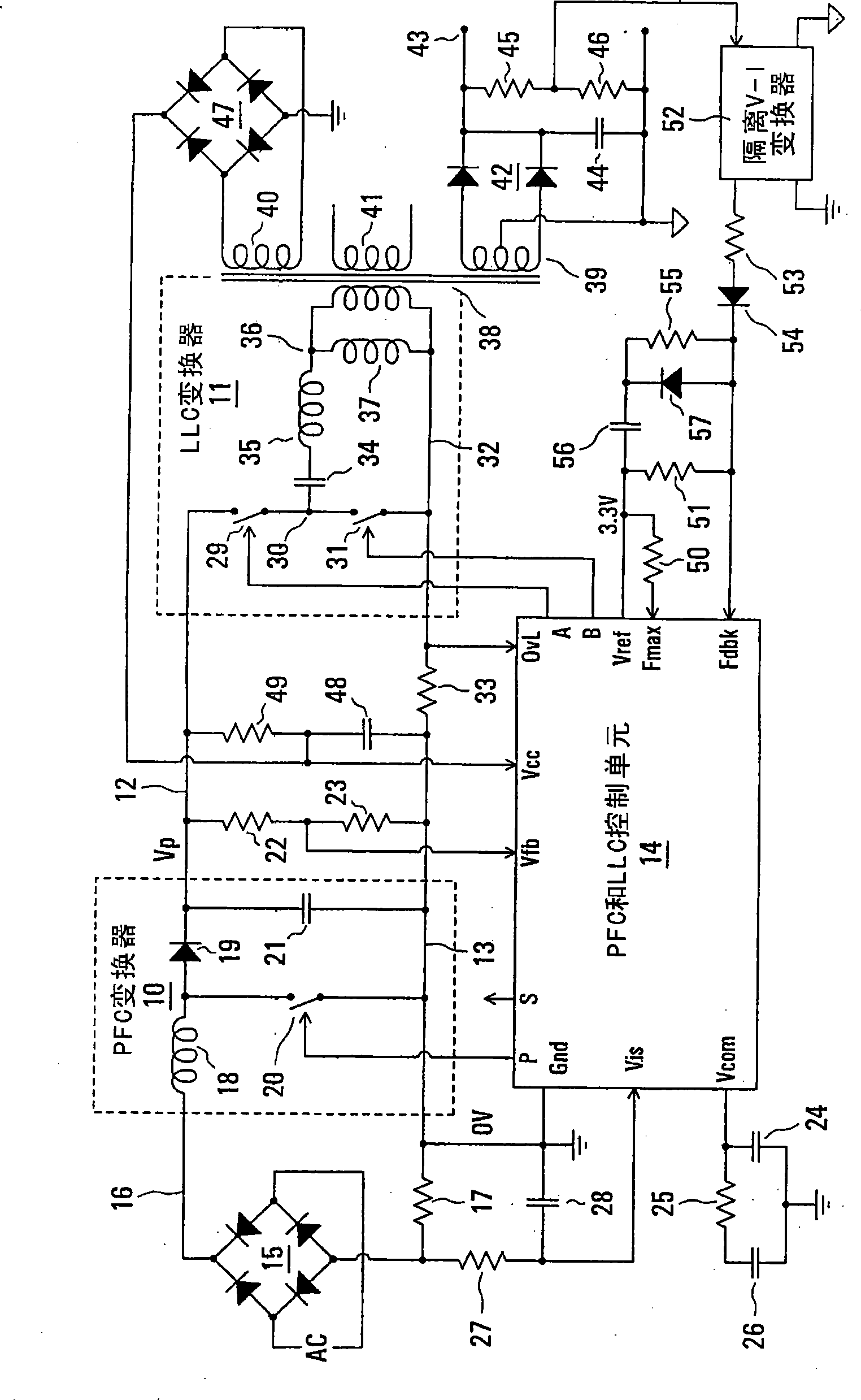
[0036] Such as figure 1 The illustrated power supply arrangement includes a PFC power converter 10 and an LLC power converter 11 , which are shown within dashed boxes. Converters 10 and 11 are cascaded, and the positive output voltage Vp of PFC converter 10 developed on line 12 relative to zero volt (0V) line 13 connected to ground is connected as shown for LLC converter 11. Input voltage. The cascaded PFC power converter 10 and LLC power converter 11 are controlled by a PFC and LLC control unit 14 having a ground connection Gnd connected to line 13, as will be further described below.

[0037] The AC power supplied to the input of the power supply arrangement is rectified by the diode bridge 15 . The positive rectified AC output of diode bridge 15 is coupled to the positive voltage input of PFC converter 10 via line 16 and a return path is provided from 0V line 13 to diode bridge 15 via current sense resistor 17 . For example, depending on the voltage of the AC power sourc...


PUM


Abstract

The switching frequency of an LLC converter is controlled by a control unit to which a feedback circuit provides a first current dependent upon the output voltage of the converter. An oscillator circuit produces a sawtooth waveform at a frequency dependent upon the first current, up to a limit equal to a second current set by a resistor. Two complementary switch control signals are produced for controlling two switches of the converter for conduction in alternate cycles of the sawtooth waveform. A timer produces dead times between the two complementary switch control signals in dependence upon the second current. Another resistor provides a current constituting a minimum value of the first current, and a charging current of a capacitor in series with a resistor modifies the first current for soft starting of the converter.

Description

technical field [0001] The invention relates to a control arrangement for a resonant mode power converter. Background technique [0002] It is known to provide a cascade of a boost converter for PFC followed by a PWM (Pulse Width Modulation) buck converter to generate a lower voltage than the normally higher output voltage of the PFC converter , and operate them in a synchronous manner using a single clock reference. Such a cascaded converter is for example US Patent No. 5,565,761 entitled "Synchronous Switching Cascade Connected Off-Line PFC-PWMCombination Power Converter Controller" of Hwang authorized on October 15, 1996 and authorized on August 25, 1998 It is described in US Patent No. 5,798,635 entitled "One Pin Error Amplifier And Switched Soft-Start For An Eight Pin PFC-PWM Combination Integrated Circuit Converter Controller" by Hwang et al. [0003] Another arrangement comprising cascaded PFC and PWM power converters is known from Fairchild Semiconductor Applicatio...

Claims


Application Information

Patent Timeline
Patent Type & Authority Applications(China)
IPC IPC(8): H02M3/28H02M1/36
CPCY02B70/1433H02M2007/4815H02M2001/007H02M3/3376Y02B70/1441Y02B70/1491H02M2001/0058H02M1/0058H02M1/007Y02B70/10
Inventor 安东尼·瑞恩伯格保罗·戴莫奈
Owner POWER INTEGRATIONS INC
Why Eureka
Try Eureka