Bearing device for wheel

A bearing device, wheel technology, applied in the direction of bearings, axles, wheels, etc., can solve problems such as quenching cracks, and achieve the effect of preventing quenching cracks and prolonging life.

Active Publication Date: 2009-08-12
NTN CORP
View PDF1 Cites 2 Cited by
  • Summary
  • Abstract
  • Description
  • Claims
  • Application Information

AI Technical Summary

Problems solved by technology

[0011] Conversely, if the wall thickness of the outer member 51 is excessively reduced in order to reduce the weight of the outer member 51, it will cause a problem that quenching occurs when the outer raceway surfaces 51a, 51b are formed with hardened layers by high-frequency induction hardening. crack

Method used


Image

  • Bearing device for wheel
  • Bearing device for wheel
  • Bearing device for wheel

Examples


no. 1 approach

[0117] Preferred embodiments of the present invention will be described below with reference to the accompanying drawings.

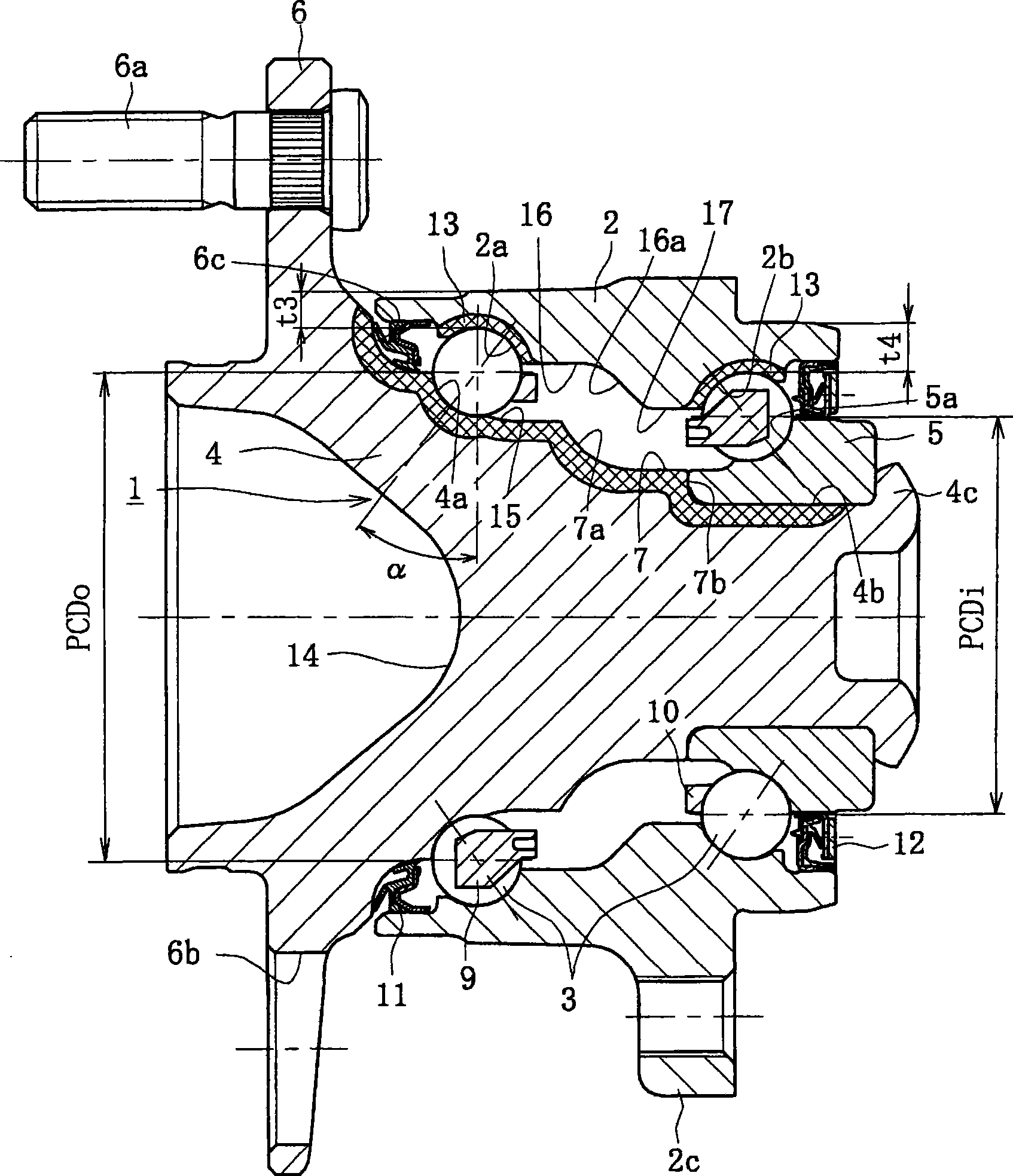
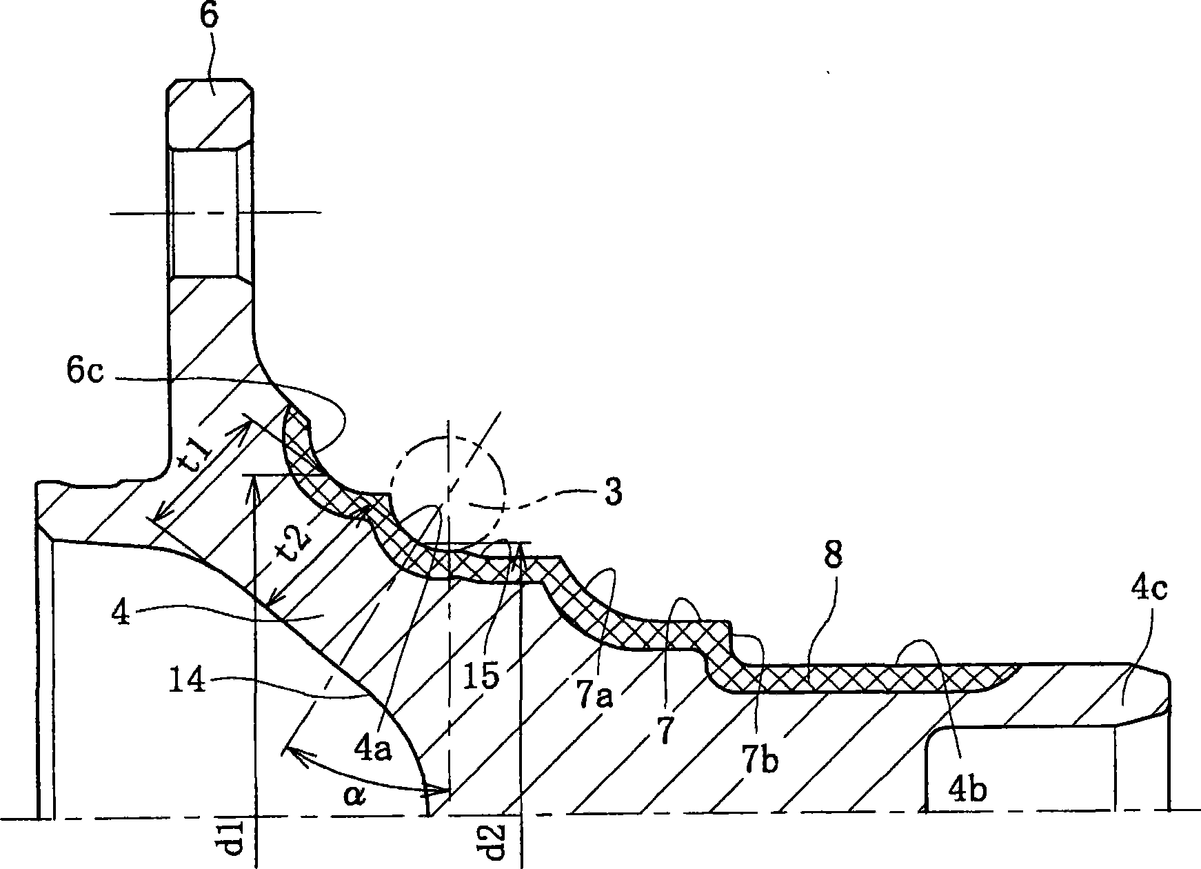
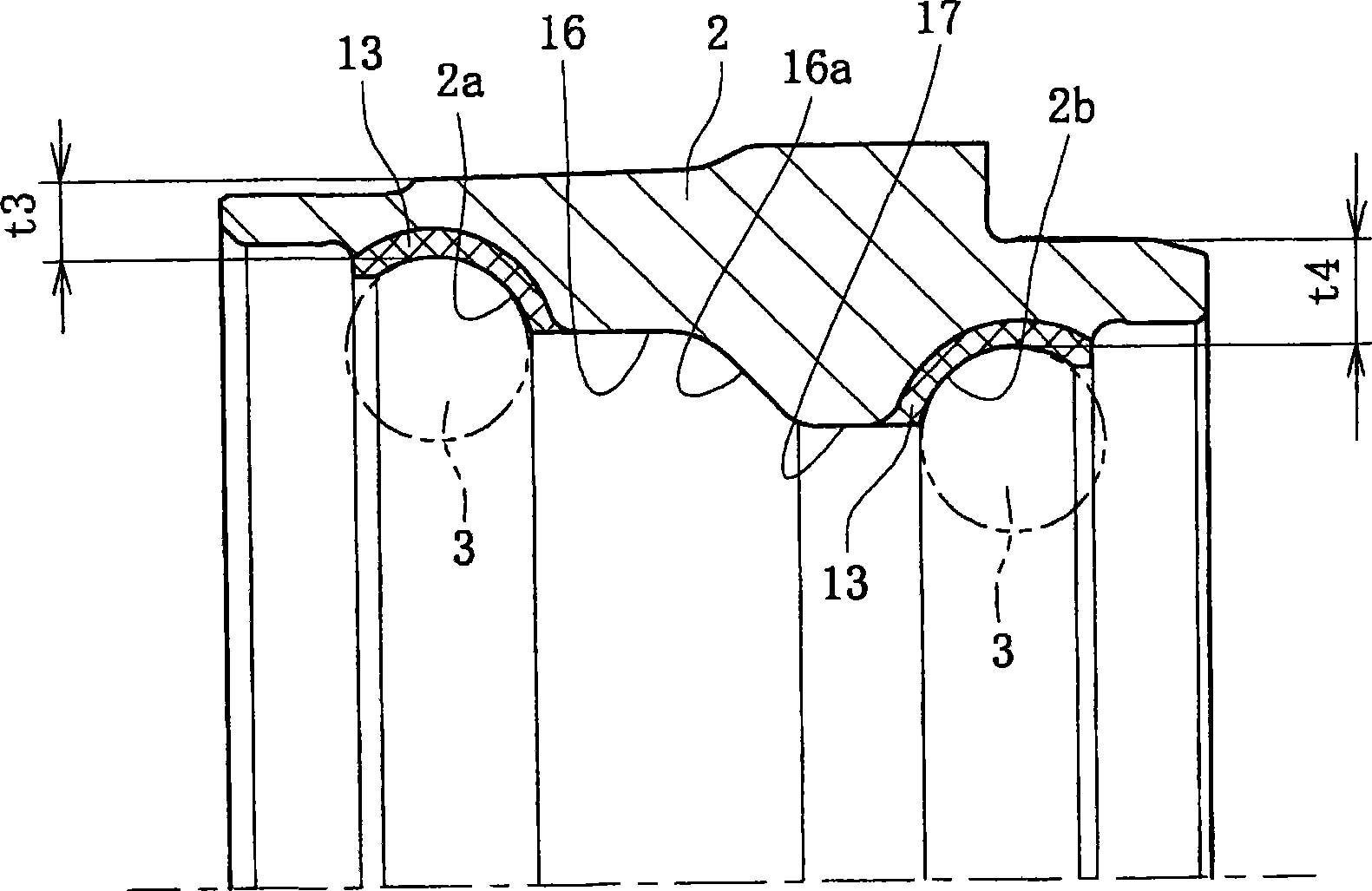
[0118] figure 1 It is a longitudinal sectional view showing the first embodiment of the wheel bearing device of the present invention, figure 2 yes figure 1 The enlarged longitudinal section of the hub wheel, image 3 yes figure 1 An enlarged longitudinal sectional view of the outer part of the Figure 4 (a) is figure 1 A longitudinal section of the outer part of the after its forging, Figure 4 (b) is Figure 4 A longitudinal sectional view of a modified example of (a), Figure 5 yes figure 1 Illustrative longitudinal section of the wheel hub after it has been forged.

[0119] figure 1 The wheel bearing device of the present invention shown is of the third generation type for driven wheels and comprises an inner part 1, an outer part 2 and a double row of rolling elements rotatably accommodated between the inner part 1 and the outer par...

no. 2 approach

[0142] Figure 6 is a longitudinal sectional view showing a second embodiment of the wheel bearing device of the present invention, Figure 7 yes Figure 6 An explanatory longitudinal sectional view of a bearing device for a wheel of , showing a grease filling step. Since the second embodiment partly differs from the first embodiment only in the structure of the hub wheel, the same reference numerals are used here to denote the same components having the same functions as those used in the first embodiment.

[0143] This wheel bearing device is of the third generation type for driven wheels and includes an inner part 26 , an outer part 2 and a double row ball set 3 , 3 accommodated freely rolling between the inner part 26 and the outer part 2 . The inner member 26 includes a wheel hub 27 and the inner ring 5 press-fitted on the wheel hub 27 with a predetermined interference.

[0144] Hub wheel 27 is integrally formed with wheel mounting flange 6 at its outer end, one (outer...

no. 3 approach

[0152] Figure 8 is a longitudinal sectional view showing a third embodiment of the wheel bearing device of the present invention, Figure 9 (a) means Figure 8 Front view of the machining method of the outer part, Figure 9 (b) is along Figure 9 (a) Longitudinal sectional view taken along line IX-IX. Since the third embodiment and the second embodiment ( Figure 6 ) partly differs only in the structure of the outer parts, so the same reference numerals are used here to designate the same parts with the same functions as those used in the previous embodiments.

[0153]This wheel bearing device is of the third generation type for driven wheels and includes an inner part 26 , an outer part 29 and a double row ball set 3 , 3 accommodated freely rolling between the inner part 26 and the outer part 29 . The outer member 29 is integrally formed on its outer periphery with a body mounting flange 2c to be mounted on the aluminum alloy steering knuckle N, and is integrally formed...


PUM


Abstract

To provide a bearing device for a wheel, which could have realized a prolonged service life of the bearing by solving contradictory problems of a weight reduction/higher level of compactness and a higher level of rigidity. [MEANS FOR SOLVING PROBLEMS] A bearing device for a wheel, comprising a double-row angular ball bearing having three groups of double-row balls (3). Among the three groups of double-row balls (3), the pitch diameter PCDo of the outer-side group of balls (3) is set to a value larger than the pitch diameter PCDi of the inner-side group of the balls (3). At the same time, an outer member (2) is formed of a medium to high carbon steel containing 0.40 to 0.80% by weight of carbon. Double-row outer rolling faces (2a, 2b) have a predetermined hardened case (13) having a surface hardness range of 58 to 64 HRC formed by high frequency hardening. The effective hardening depth of the hardened case (13) is set to at least 2 mm, and the minimum thickness (t3, t4) of this site isset to at least 4 mm.

Description

technical field [0001] The present invention relates to a bearing device for a wheel, and more particularly to a bearing device for a wheel, which can solve the conflicting problems of reducing the weight and size of the bearing device and prolonging the life of the bearing device. Background technique [0002] Generally, the bearing device for a wheel is adapted to freely rotatably support a hub wheel for mounting a wheel through a rolling bearing, and adopts an inner ring rotation type for a driving wheel and an inner ring rotation type and an outer ring rotation type for a driven wheel. Double row angular contact ball bearings are widely used in such bearing devices because of their desired bearing rigidity, high misalignment resistance, and small torque required for low fuel consumption. A double row angular contact ball bearing has a plurality of balls interposed between a stationary ring and a rotating ring, and the balls are in contact with the stationary ring and the...

Claims


Application Information

Patent Timeline
Patent Type & Authority Applications(China)
IPC IPC(8): B60B35/02B60B27/00F16C19/18F16C19/38F16C33/58F16C33/62
Inventor 龟高晃司大槻寿志小森和雄
Owner NTN CORP
Why Eureka
Try Eureka