
Steam turbine designed to facilitate late modification for operation with power plant incorporating carbon capture facilities

A steam turbine, turbine technology, applied in the direction of engine components, machines/engines, mechanical equipment, etc., can solve the problem of carbon capture and sequestration technology not fully developed, reducing efficiency, not equipped with carbon capture, etc.

Inactive Publication Date: 2009-08-12
GENERAL ELECTRIC TECH GMBH
View PDF0 Cites 3 Cited by
  • Summary
  • Abstract
  • Description
  • Claims
  • Application Information

AI Technical Summary

Problems solved by technology

Unfortunately, carbon capture and sequestration is not yet fully developed
Furthermore, designing power plants to capture the carbon they produce is likely to significantly reduce their efficiency
As a result, most fossil fuel power plants are still built without future carbon capture

Method used


Image

  • Steam turbine designed to facilitate late modification for operation with power plant incorporating carbon capture facilities
  • Steam turbine designed to facilitate late modification for operation with power plant incorporating carbon capture facilities

Examples


Embodiment Construction

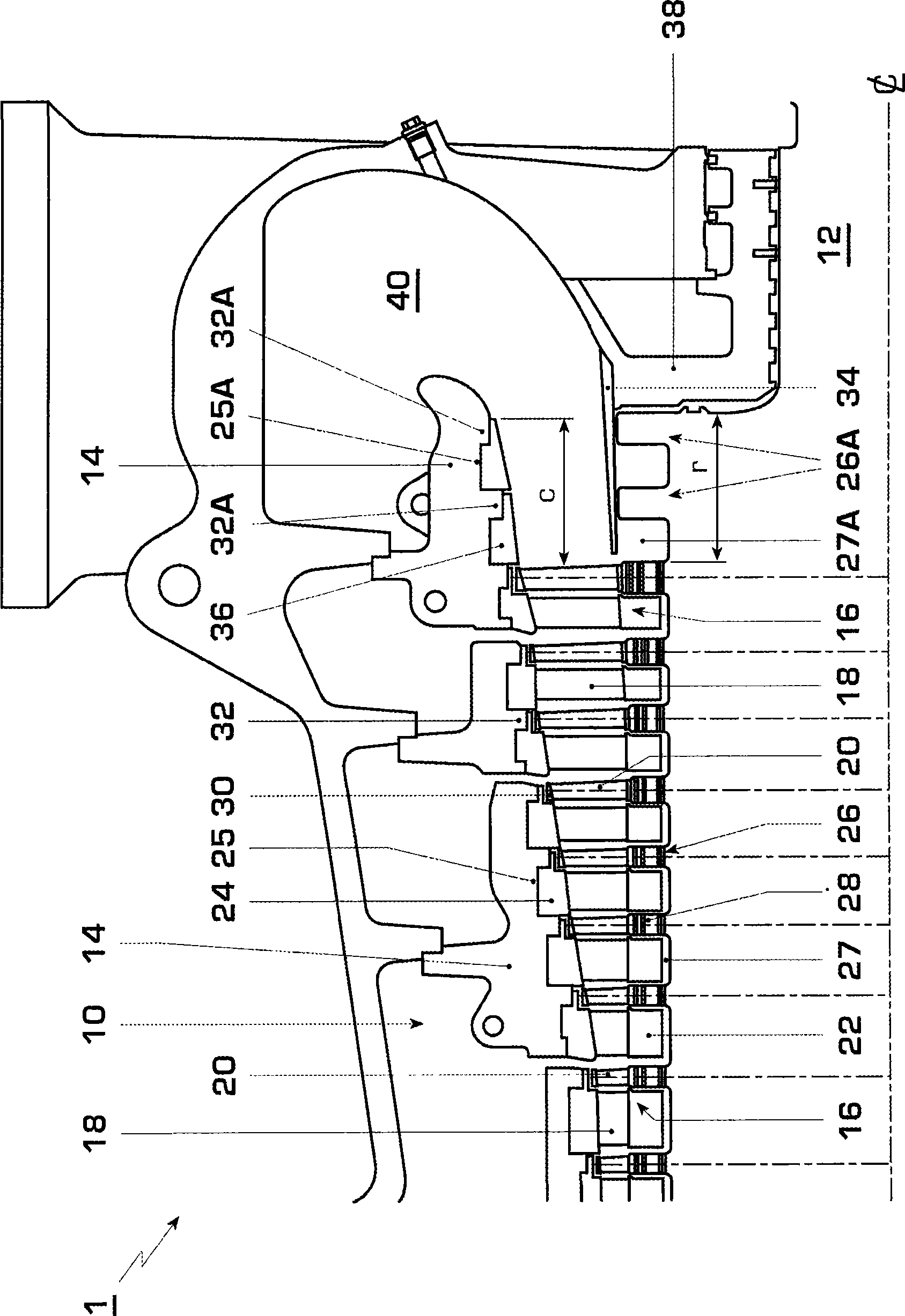
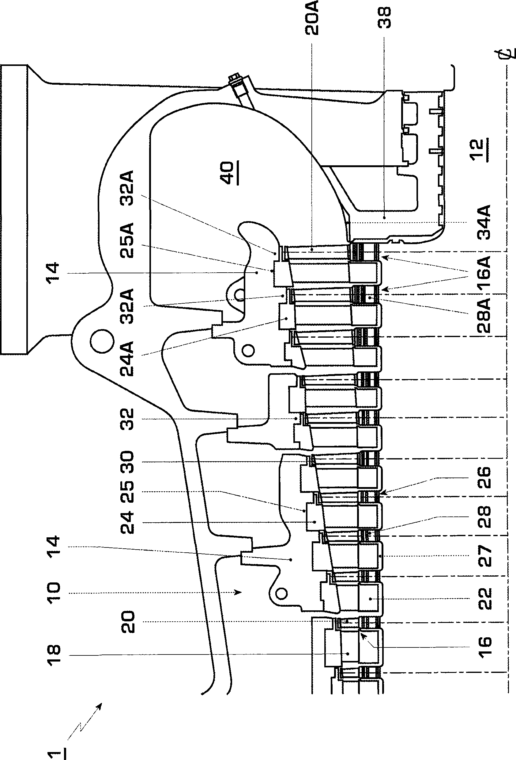
[0019] Briefly, a preferred embodiment of the invention includes a steam turbine for a fossil fuel power plant that facilitates carbon capture. The turbines include intermediate pressure (IP) turbines manufactured to operate at a specific expansion ratio and supply the low pressure turbine at a specific steam volumetric flow rate. The IP turbine is made with extra length in its rotor and casing to allow the subsequent addition of additional turbine stages to increase the turbine expansion ratio at its outlet and volume flow rate. After adding an additional stage, the resulting additional volume flow rate of process steam can be vented from the IP turbine outlet to feed the post combustion carbon capture process without affecting the ability of the IP turbine to supply the low pressure turbine with the original volume flow rate of steam.

[0020] now refer to figure 1 , an axial flow steam turbine 1 is part of a "facilitated carbon capture" fossil fuel power plant, where the ...


PUM


Abstract

A steam turbine 1 for a carbon-capture ready fossil fuel power plant includes an intermediate pressure (IP) turbine 10 manufactured to operate with a particular expansion ratio and supply a low pressure turbine with a particular volumetric flow rate of steam. The IP turbine 10 is manufactured with extra lengths r and c in its rotor 12 and casing 14 to enable the later addition of extra turbine stages effective to increase the turbine's expansion ratio and volumetric flow rate at its exit without increasing its overall as-manufactured length. After addition of the extra stages, the additional volumetric flow of process steam can be bled off from the IP turbine exit to service a post- combustion carbon-capture process, without affecting the ability of the IP turbine to supply the original volumetric flow rate of steam to the low pressure turbine.

Description

technical field [0001] The present invention relates to steam turbines, and in particular to steam turbines designed to facilitate subsequent retrofitting to work with power plants that include carbon capture facilities. Background technique [0002] Recently, there has been a growing consensus that global warming and the resulting climate change are serious threats to future socioeconomic stability. This has sparked interest in carbon capture and storage - so-called "carbon sequestration" - as a way to sustain the use of fossil fuels without releasing carbon dioxide into the atmosphere. Unfortunately, carbon capture and sequestration technology is not yet fully developed. Furthermore, designing power plants to capture the carbon they produce is likely to significantly reduce their efficiency. Thus, most fossil fuel power plants are still built without future carbon capture. Therefore, the government is likely to create regulations and / or provide incentives so that power ...

Claims


Application Information

Patent Timeline
Patent Type & Authority Applications(China)
IPC IPC(8): F01D25/24F01D5/02
CPCF01D25/24F05D2230/51F05D2220/31F01D5/02F05B2220/301Y10S415/912Y10T29/49238Y10T29/49233Y10T29/49323Y10T29/49716
Inventor M·R·洛德P·D·赫姆斯利
Owner GENERAL ELECTRIC TECH GMBH
Learn More