
Equipment room ventilation purification plant

A technology of purification device and air outlet device, which is applied in ventilation systems, space heating and ventilation, heating and ventilation hoods/covers, etc., can solve the problems of communication and telecommunication base stations not working properly, consuming large amounts of power, and intermittently shutting down, etc. To achieve the effect of lowering temperature, lowering operating costs, and reducing power consumption

Inactive Publication Date: 2009-08-19
POWERCITY ELECTROMECHANICAL & EQUIP
View PDF0 Cites 13 Cited by
  • Summary
  • Abstract
  • Description
  • Claims
  • Application Information

AI Technical Summary

Problems solved by technology

[0002] Since the communication and telecommunications base stations and unattended computer rooms are fully enclosed computer rooms, the power supply equipment, transmitting equipment, and transmission equipment in the computer room will generate a lot of heat. The temperature is too high, resulting in intermittent shutdown or even damage
The reason is that, firstly, the equipment operates in a closed room for a long time for dust prevention and pollution reduction; secondly, when the external power supply is suddenly interrupted, the air conditioner will stop immediately, which will cause the communication and telecommunication base stations to fail to work normally, resulting in serious consequence
Moreover, the air conditioner used for cooling must run continuously all the year round, and consumes a large amount of electric energy.

Method used


Image

  • Equipment room ventilation purification plant
  • Equipment room ventilation purification plant
  • Equipment room ventilation purification plant

Examples


Embodiment Construction

[0020] Below in conjunction with accompanying drawing and embodiment the present invention will be further described:

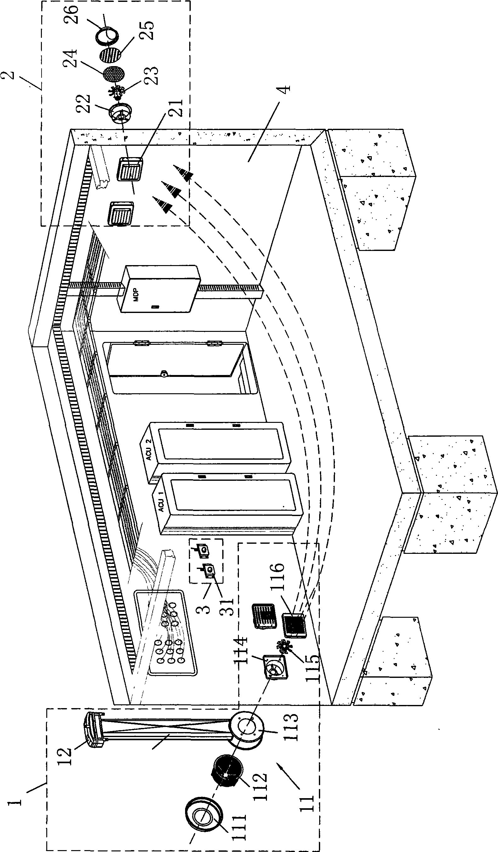
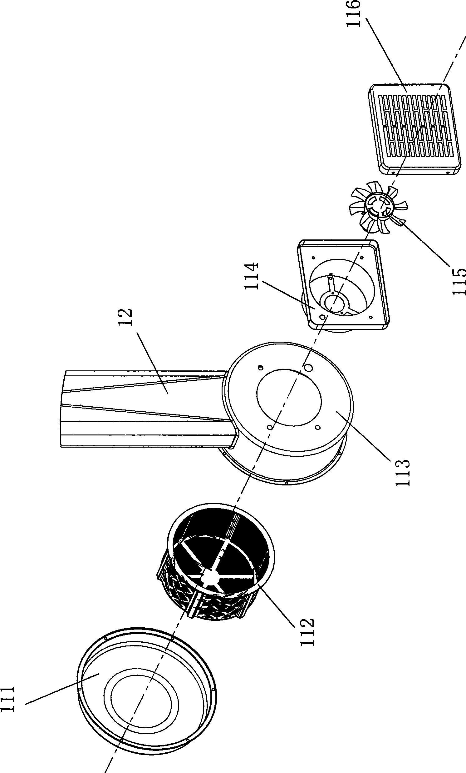
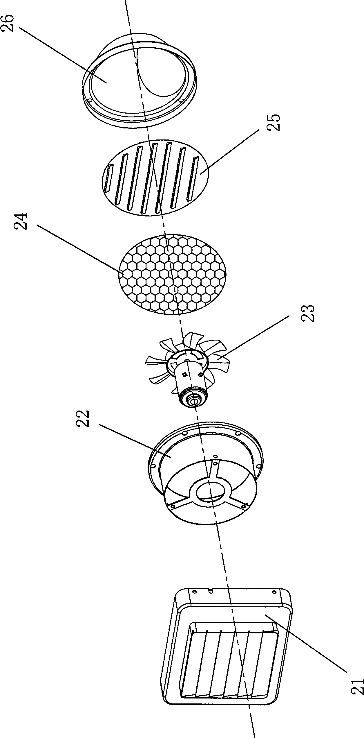
[0021] Such as figure 1 , figure 2 and Figure 4 As shown, this embodiment includes an air inlet device 1 , an air outlet device 2 and a temperature control system 3 , and the air inlet device 1 is composed of an air inlet mechanism 11 and an air duct 12 . This air duct pipe 12 is vertically installed on the outer sidewall of machine room 4 walls, and the upper end of air duct pipe 12 is open, is covered with rainproof cover 13 above air duct pipe 12, and air inlet 131 is arranged on rainproof cover 13 bottoms ( Figure 6 Its enlarged view), the lower end of the air duct pipe 12 is connected with the air inlet mechanism 11. The air intake mechanism 11 is made up of an air filter cover 111 , an air filter 112 , an air filter seat 113 , a fan seat 114 , an air intake DC fan 115 and an air intake protective cover 116 . The air filter cover 111 and the air ...


PUM


Abstract

The invention provides a device in a machine room for ventilation and purification, comprising a wind inlet device, a wind outlet device and a temperature-control system; the wind inlet device consists of a wind inlet mechanism and a wind duct pipe; the wind duct pipe is arranged on the external side wall of the machine room wall; the upper end of the wind duct pipe is open for air inlet and the lower end thereof is connected with the wind inlet mechanism; the wind inlet mechanism is internally provided with an air filter and a wind inlet DC fan; the air filter is arranged at the outlet of the lower end of the wind duct pipe; the wind inlet DC fan extends along the central line direction of the air filter and is arranged in the wind inlet opened on the machine room wall; the wind outlet device is provided with a wind outlet DC fan which is arranged in the wind outlet opened on the machine room wall; and the wind outlet is higher than the wind inlet by at least 1 meter. The device can replace the air conditioner in the machine room, can reduce the temperature in the machine room, can ensure that the base station equipment can run safely, reliably and stably, and can greatly reduce the electric energy consumption, thus greatly reducing the running cost of the communication and telecommunication enterprises; simultaneously, the device has active propulsion function on the energy-saving and emission reduction, environmental protection and ecology.

Description

technical field [0001] The invention relates to a ventilation device, in particular to a ventilation and purification device for a machine room. Background technique [0002] Since the communication and telecommunications base stations and unattended computer rooms are fully enclosed computer rooms, the power supply equipment, transmitting equipment, and transmission equipment in the computer room will generate a lot of heat. The temperature is too high, resulting in intermittent shutdown or even damage. The reason is that, firstly, the equipment operates in a closed room for a long time for dust prevention and pollution reduction; secondly, when the external power supply is suddenly interrupted, the air conditioner will stop immediately, which will cause the communication and telecommunication base stations to fail to work normally, resulting in serious consequence. Moreover, the air conditioner used for cooling must run continuously all the year round, and consumes a lar...

Claims


Application Information

Patent Timeline
IPC IPC(8): F24F7/10F24F13/28F24F11/02F24F13/20
Inventor 赖加亮
Owner POWERCITY ELECTROMECHANICAL & EQUIP
Learn More