Wave wafer, manufacturing method, mold and liquid crystal panel

A manufacturing method and wave chip technology, which are applied in optics, instruments, nonlinear optics, etc., can solve the problems of increased cost, increased light loss, discomfort, etc., and achieve the advantages of being easy to use and carry, reducing visual fatigue, and improving quality Effect

Active Publication Date: 2011-02-09
KUSN INFOVISION OPTOELECTRONICS
View PDF0 Cites 0 Cited by
  • Summary
  • Abstract
  • Description
  • Claims
  • Application Information

AI Technical Summary

Problems solved by technology

Because different wavelengths of light correspond to different colors, and the polarizer on the liquid crystal as a display device must display a variety of different colors at the same time, so using the wave chip of the prior art, only a certain specific The light of one color is circularly polarized light, while the light of other colors does not contain circularly polarized light at all, which is likely to cause fatigue and discomfort to the human eye.
Therefore, this wave chip with fixed light wavelength is not suitable for display devices, and its application range is limited.
In other designs of broadband wave chips, several wave chips with different fixed light wavelengths are superimposed. This method will increase the cost, increase the loss of light, and reduce the utilization efficiency of light.

Method used


Image

  • Wave wafer, manufacturing method, mold and liquid crystal panel
  • Wave wafer, manufacturing method, mold and liquid crystal panel
  • Wave wafer, manufacturing method, mold and liquid crystal panel

Examples


Embodiment Construction

[0051] In order to make the object, technical solution and advantages of the present invention clearer, the present invention will be further described in detail below with reference to the accompanying drawings and examples.

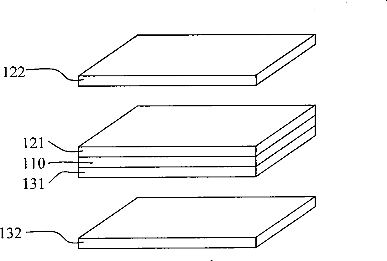
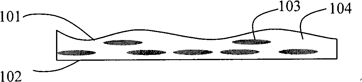
[0052] The present invention is aimed at broadband wavelength light design, and the wave chip is designed as a shape of thickness change, and the minimum thickness and maximum thickness are respectively designed according to the minimum and maximum light wavelengths of broadband wavelength light, so that the minimum light wavelength is transmitted through the minimum thickness of the wave chip. The phase difference of e light and the phase difference of o light and e light at the place where the maximum light wavelength passes through the maximum thickness are both Odd multiples of , so that there is a corresponding position for any wavelength of light so that the phase difference is Odd multiples, the outgoing light changes from linearly polarized li...


PUM


Abstract

The invention discloses a wave wafer which is designed for linearly polarized light of wide band wavelength; the thickness of the wave wafer is changeable, the phase difference between o light and e light when the minimum wavelength permeates through the minimum thickness and the phase difference between o light and e light when the maximum wavelength permeates through the maximum thickness are both odd number of times of half of Pi, thus leading light with any wavelength to exist at a certain corresponding position so as to lead the phase difference to be odd number of times of half of Pi, therefore, the emergent light is converted from linearly polarized light to circularly polarized light. The invention also discloses a method for manufacturing the wave wafer, and a mold thereof; the wave wafer manufactured by adopting the method and the mold is light, thin and soft, convenient for carrying, and can lead lights with any wavelength to contain the circularly polarized light after thelinearly polarized light of the wide band passes through. The invention simultaneously discloses a liquid crystal panel which contains the wave wafer, and all the lights with any wavelength in the emergent light of the liquid crystal panel contain the circularly polarized light, thereby reducing the visual fatigue of viewers.

Description

technical field [0001] The invention relates to optical polarization technology, in particular to a wave plate, a manufacturing method, a mold, and a liquid crystal panel using the wave plate. Background technique [0002] At present, with the continuous development of display technology, thin film transistor liquid crystal display (TFT-LCD) with high quality, low power consumption, small size, and no radiation has been widely used and has become the mainstream of the market. Small electronic products with display screens such as game consoles, electronic dictionaries, and digital cameras, as well as products such as notebook computers, monitors, and LCD TVs that appear on the market at present, liquid crystal display has become a mainstream display technology that is well known to the public and widely used. [0003] With the accelerated development of social informatization, people's acquisition and utilization of information is becoming more and more intense in daily work...

Claims


Application Information

Patent Timeline
Patent Type & Authority Patents(China)
IPC IPC(8): G02B5/30G02F1/1335
Inventor 徐富国邱郁雯
Owner KUSN INFOVISION OPTOELECTRONICS
Why Eureka
Try Eureka