

Apparatus and method for conditioning an immersion fluid
A flow path and feeding technology, which is applied in photolithography exposure devices, microlithography exposure equipment, etc., can solve problems such as watermark defects and difficulty in keeping the wafer surface dry
- Summary
- Abstract
- Description
- Claims
- Application Information
AI Technical Summary
Problems solved by technology
Method used
Image

Examples
Embodiment 1
[0100]This example illustrates the results of using a single silica purifier, Type I strong base anion resin, to remove silica from water in a single pass procedure. The results show that a single purifier demonstrated greater than 70% dissolved silica removal efficiency with a 0.33 ppb dissolved silica feed into the purifier.
[0101] The amount of dissolved silica was observed to be less than 0.05 ppb (detection limit) at the purifier outlet after 1 and 6 days. It was observed that the dissolved silica removal efficiency increased as the flow rate increased. Without being bound by any theory, the higher flow rate is believed to minimize channeling in the purifier bed and provide good contact between the water and resin.
[0102] No appreciable amount of TOC elutes from the Si purifier resin.
Embodiment 2
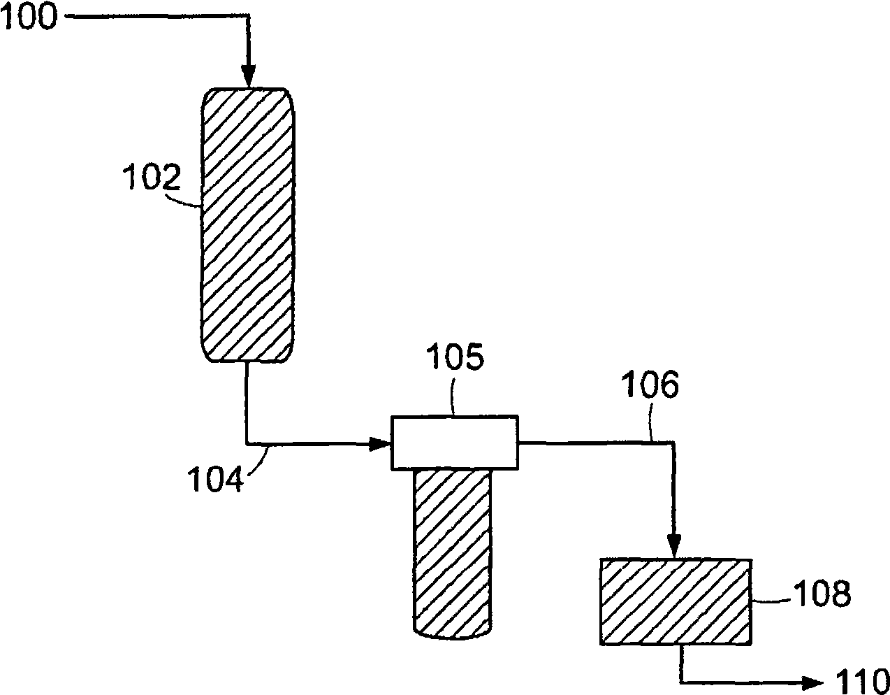
[0104] This embodiment provides as figure 2 Test results of a specific mode of the described device. figure 2 A single pass purification process is shown wherein the impregnation fluid 100 in this example, deionized water of the main loop, is introduced into a purifier 102 . Purifier 102 is a Si purifier. Purified water stream 104 from purifier 102 is directed through particle filter 105 . Particle filter 105 is 0.02 micron Z filter. Filtered water stream 106 is directed from particle filter 105 to particle counter 108 (UDI 50). Samples were collected after the particle count had slowed and stabilized.
[0105] Figure 3A Shown is the total silica content (ppb) for the primary loop deionized water (200), purified water stream 104 (202) and filtered water stream 106 (204). The overall silica removal efficiency was about 60% for a single pass. Figure 3B The dissolved silica content (ppb) is shown for the main loop deionized water (206), the purified water stream 104...
Embodiment 3
[0110] This example describes an experiment in which a filter was used to refine the process. This example uses Figure 4 device described in . Domestic ionized (DI) water 300 is combined with a recirculated water stream 302 to form a combined stream 304 that is directed to a pump 306 . Pump 306 delivers combined stream 304 to degassers 308 and 310 . Degassed water stream 312 is directed to UV oxidation units 314 and 316 . The resulting UV-treated water stream 318 is then directed to II High Purity Degasser 320. Resulting water stream 322 is directed to Si purifier 324 and mixed bed purifiers 326 and 328 to produce purified stream 330 . Purified stream 330 is then directed to Z 0.02 micron cartridge filter 332 to generate filtered water stream 334 . Filtered water stream 334 is then directed to heat exchangers 336 and 338 . Heat exchangers 336 and 338 are supplied using cooling water 340 provided by cooler 342 (eg, NESLAB cooler). Stream 344 is used to collect a l...
PUM
 Abstract
Description
Claims
Application Information