Multi-wavelength laser

A technology of multi-wavelength lasers and laser arrays, applied in the field of lasers, can solve problems such as direct modulation and internal modulation, and achieve the effects of stable refractive index, convenient use, and large channel number capacity

Inactive Publication Date: 2004-03-03
柳钟山
View PDF1 Cites 0 Cited by
  • Summary
  • Abstract
  • Description
  • Claims
  • Application Information

AI Technical Summary

Problems solved by technology

The laser can generate stable wavelength spacing, but cannot directly modulate and internally modulate each wavelength

Method used


Image

  • Multi-wavelength laser
  • Multi-wavelength laser
  • Multi-wavelength laser

Examples


Embodiment Construction

[0023] The present invention will be further described below in conjunction with the embodiments given in the drawings.

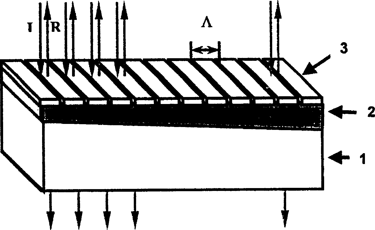
[0024] First, before describing the various embodiments, the principle of the present invention is introduced. The principle of the wavelength-selectable optical device as the wavelength-selectable feedback mirror is guided-mode resonance. When a waveguide mode that may be supported by the waveguide without refractive index modulation appears in a waveguide grating, a waveguide mode oscillation will be generated in the waveguide grating. However, because there is periodic refractive index modulation or perturbation in or around the grating waveguide. Optical transmission constant β in the waveguide i (See formula 2) becomes a complex number. The imaginary part cannot be ignored. As a result, the waveguide mode cannot be transmitted without loss in the waveguide. This structure is called the "drain" structure. In this "drain" structure, the energy of the inciden...


PUM


Abstract

This invention provides a multi-wavelength laser composed of a laser and wavelength selectable device designed with an nonuniformiy structure which can reflect the light of different wavelengths from different positions on the operation surface when the wavelength selectable light device is used as the feedback mirror of the laser array, it can feedback the light of different wavelengths along the nonuniformity direction at different positions to the laser units in the relative array and matrix of the position so as to generate laser oscillating.

Description

Technical field [0001] The invention relates to the field of laser technology, in particular to a multi-wavelength laser. Background technique [0002] Multi-wavelength lasers can be used to provide multi-channel light sources for optical fiber networks, especially dense wavelength division multiplexing (DWDM) systems. For multi-wavelength lasers used in DWDM fiber systems, the desired characteristics are compact structure, stable output wavelength and wavelength interval, a certain output power, wide wavelength range and narrow line width to achieve a large number of channel capacity. Each wavelength can be easily modulated at a high rate. In addition, the wavelength locking mechanism of the laser source should be as simple as possible. Due to the limitations of current laser technology, there is no multi-wavelength laser that can meet these characteristics. [0003] Known multi-wavelength lasers can be roughly divided into two categories: multi-wavelen...

Claims


Application Information

Patent Timeline
Patent Type & Authority Patents(China)
IPC IPC(8): G02B6/00H01S3/23H01S5/00H01S5/02
Inventor 柳钟山
Owner 柳钟山
Why Eureka
Try Eureka