

Optimal-friction-resistance cast-in-place pile type and construction method therefor
A cast-in-situ pile and frictional resistance technology, which is applied in sheet pile walls, foundation structure engineering, construction, etc., can solve the problems of declining profit margins and increasing comprehensive costs of construction enterprises, and achieve saving in shipping costs, improving the bearing capacity of single piles, The effect of saving construction investment
- Summary
- Abstract
- Description
- Claims
- Application Information
AI Technical Summary
Problems solved by technology
Method used
Image

Examples
Embodiment Construction
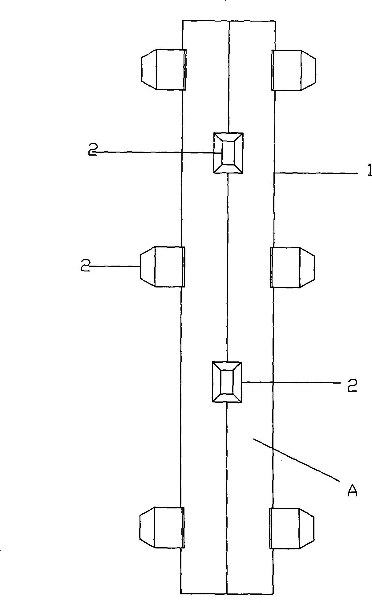
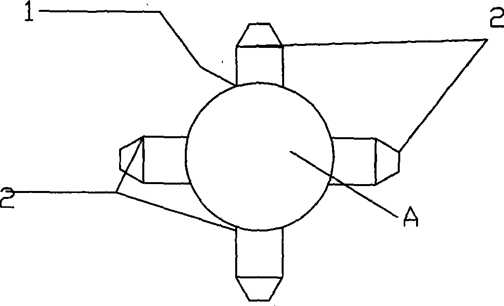
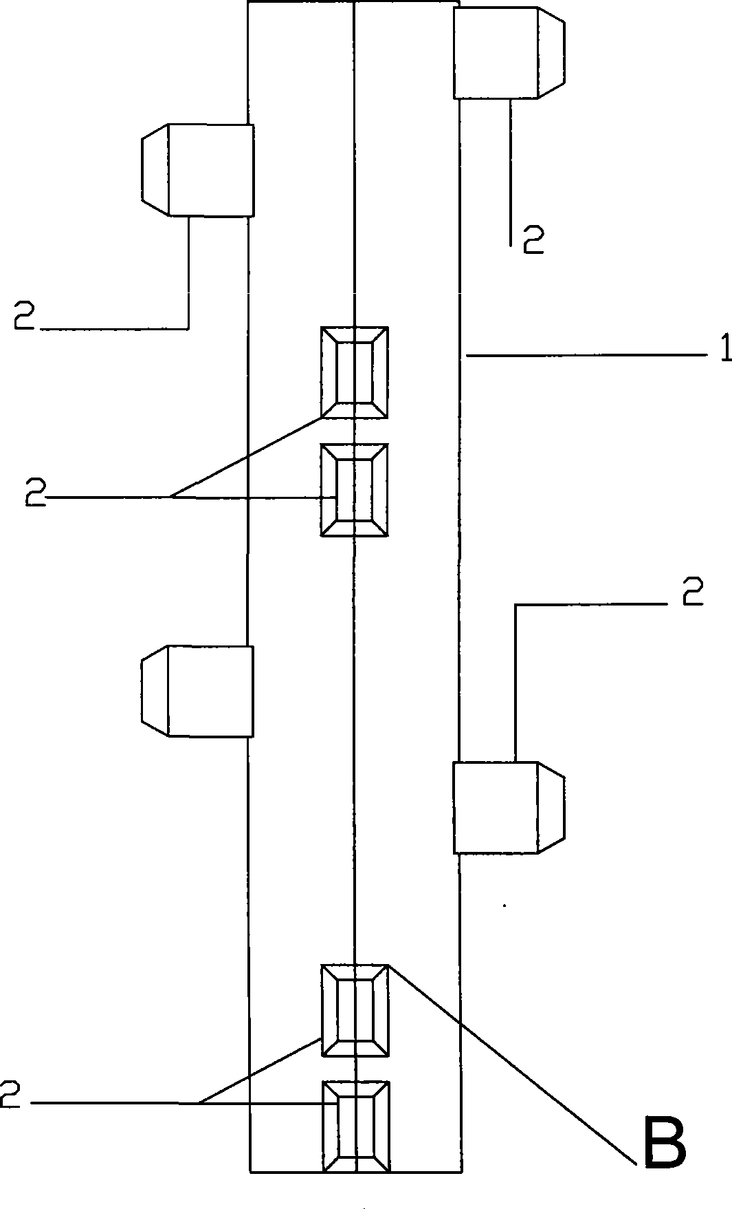
[0017] The optimized friction resistance cast-in-situ pile type made by the pile expanding machine has three forms, which are characterized by protruding pairs of rectangular pile cones on the cylindrical pile body, which are perpendicular to the axis, radially symmetrical or staggered; Figure 1a , Figure 1b The cast-in-situ pile type A shown in the first type is a pair of protruding rectangular pile cones 2 on the cylindrical pile body 1, each pair is radially horizontally symmetrical, vertically intersects the center of the circle, and is staggered in the axial direction of the pile body; Figure 2a , Figure 2b The second type of multiple sets of rectangular pile cones 2 of cast-in-situ pile type B shown is that the two pile cones of each pair of rectangular pile cones are staggered with each other in the axial direction of the pile body 1 to the height of a rectangular pile, respectively symmetrical to the same Diameter, two pairs perpendicular to the center of the circl...
PUM
 Abstract
Description
Claims
Application Information