Spatial carrier based interference confocal measuring device and method

A measurement device, confocal technology, applied in the direction of measurement devices, optical devices, instruments, etc., can solve the problems of time-consuming, large environmental impact, etc., and achieve the effect of overcoming the difference in surface reflectance

Inactive Publication Date: 2009-09-02
HARBIN INST OF TECH
View PDF1 Cites 26 Cited by
  • Summary
  • Abstract
  • Description
  • Claims
  • Application Information

AI Technical Summary

Problems solved by technology

[0007] The invention not only retains the advantages that the phase-shift confocal detection method is not affected by the difference of the measured surface reflectance and the measurement of the workpiece tilt and the change of the curved surface profile, but also overcomes the need for multi-step phase shift in the time-shifted confocal detection, which takes a long time and is affected by The disadvantage of large environmental impact is suitable for ultra-precise, dynamic and high-speed measurement of the three-dimensional shape of microstructures

Method used


Image

  • Spatial carrier based interference confocal measuring device and method
  • Spatial carrier based interference confocal measuring device and method
  • Spatial carrier based interference confocal measuring device and method

Examples


Embodiment Construction

[0024] The present invention is described in detail in conjunction with accompanying drawing:

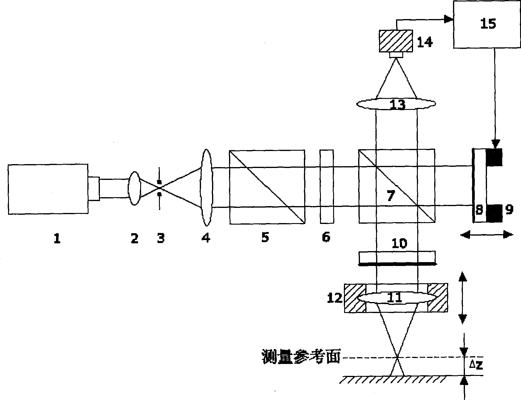
[0025] Such as figure 1 As shown, the interferometric confocal measurement device based on the space carrier of the present invention includes: a laser 1, a collimating and focusing objective lens 2, a pinhole 3, a collimating beam expanding objective lens 4, a polarizing beam splitter 5, a quarter wave plate 6, Beam splitter 7, detection focusing objective lens 11, second micro-driver 12, collecting objective lens 13; Auxiliary reference mirror 8 and first micro-driver 9 are arranged in sequence behind the beam splitter 7 along the main optical axis direction of laser 1, and main reference mirror 10 is arranged on Between the spectroscope 7 and the detection focusing objective lens 11, at the focal point of the collecting objective lens 13, a CCD camera 14 is placed, and the main control computer 15 is connected with the CCD camera 14 and the first microdriver 9.

[0026] Wherein,...


PUM


Abstract

The invention relates to a spatial carrier based interference confocal measuring device and a method, belonging to the technical filed of measurement of surface topography. The measuring device comprises a laser, a collimation focusing objective lens, a pinhole, a collimation expander objective lens, a polarization beam splitter, a quarter wave plate, a beam splitter, a detection focusing objective lens, a second microdrive and a collecting objective lens, wherein the rear side of the beam splitter along the direction of a primary optical axis of the laser is sequentially provided with an auxiliary reference lens and a first microdrive, a main reference lens is arranged between the beam splitter and the detection focusing objective lens, a CCD camera is placed on a focus position of the collecting objective lens, and a master control computer is connected with the CCD camera and the first microdrive. The method comprises the steps: establishing displacement and phase relation by a secondary confocal method, introducing a carrier signal by tilting the auxiliary reference lens, obtaining a carrier interferogram, acquiring the phase information of a measured surface by a spatial carrier phase-shifting algorithm, and finally fitting surface topography and three-dimensional profile. The invention is suitable for dynamic, quick and high-precision measurement of micro-structure three-dimensional topography.

Description

technical field [0001] The invention belongs to the technical field of surface topography measurement, and in particular relates to an ultra-precise, Dynamic, high-speed confocal measurement device and method. Background technique [0002] Confocal scanning measurement is one of the important technical means to measure three-dimensional microstructure, micro-step, micro-groove line width, depth and surface shape in the fields of micro-optics, micro-mechanics and micro-electronics. In 1957, M.Minsky proposed the basic technical idea of ​​confocal scanning measurement, which is to suppress stray light by introducing a pinhole detector and realize axial tomography. Since then, on the basis of the confocal scanning imaging technology proposed by M.Minsky, various types of confocal measurement principles such as fiber confocal microscopic measurement and differential confocal scanning measurement have been derived. [0003] Fiber confocal microscopy measurement, differential co...

Claims


Application Information

Patent Timeline
Patent Type & Authority Applications(China)
IPC IPC(8): G01B9/02G01B11/00G01B11/02G01B11/22G01B11/24
Inventor 刘俭谭久彬王伟波王宇航
Owner HARBIN INST OF TECH
Why Eureka
Try Eureka