
Method and means for producing a magnetically induced indicia in a coating containing magnetic particles

A marking and coating technology, applied in the application of magnetic films to substrates, magnetic coatings, devices for coating liquids on surfaces, etc., can solve the problems of lack of aesthetic feeling and dull appearance of images

Active Publication Date: 2009-09-02
SICPA HLDG SA
View PDF23 Cites 34 Cited by
  • Summary
  • Abstract
  • Description
  • Claims
  • Application Information

AI Technical Summary

Problems solved by technology

One of the main disadvantages, however, is that the resulting images lack aesthetics and a matte appearance, which is directly caused by the orientation of the magnetic pigment flakes perpendicular to the plane of the printed substrate over a large part of the oriented coating, which is caused by the caused by the perpendicular magnetization required by the magnetic orientation device described above

Method used


Image

  • Method and means for producing a magnetically induced indicia in a coating containing magnetic particles
  • Method and means for producing a magnetically induced indicia in a coating containing magnetic particles
  • Method and means for producing a magnetically induced indicia in a coating containing magnetic particles

Examples


Embodiment Construction

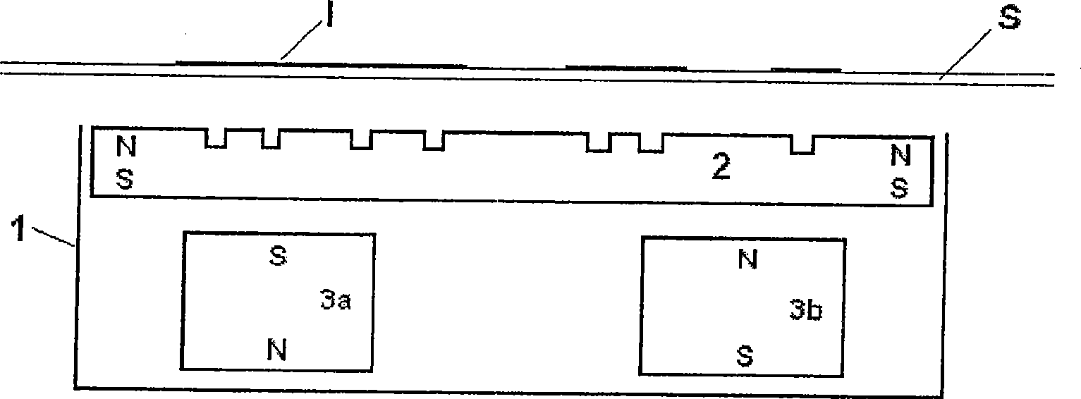
[0057] in accordance with Figure 7 , Figure 8 and specifically refer to Figure 9 In the exemplary embodiment shown, the scaffold (1) cut out of a block of aluminum is made to accommodate the SrFe 12 o 19 Two permanent magnet bars (3a, 3b) made of ceramic with dimensions 10×10×30 mm. These permanent magnets are secured and held in place by a press mechanism and screws. The poles of the two permanent magnets are Figure 7 Arrange as shown, or follow the Figure 8 Arrange as shown. An embossed permanent magnet plate (2) made of "plastic magnetic ferrite" with a size of 40 x 30 x 3 mm is arranged and fixed in place on the upper part of the permanent magnet bar so that said embossment remains accessible (i.e. seen from above).

[0058] On plastic ferrite plates, either with a mechanical engraving tool, or preferably with an automatic CO 2 Laser engraving tool or YAG laser engraving tool to engrave the desired high-resolution pattern.

[0059] The frame (1) is shaped to...


PUM


Abstract

The invention relates to a device for magnetically transferring indicia, such as a design or an image, to a wet coating layer applied on a substrate, such as a sheet or a web, wherein the said coating layer comprises at least one type of magnetic or magnetizable particles; said device comprising a) at least one magnetized permanent-magnetic plate (2) carrying relief, engravings or cut-outs, mounted such that its relief surface remains accessible, b) at least one additional magnet (3), disposed below said at least one permanent-magnetic plate, facing the surface of the magnetic plate which is opposite to the relief, engraving or cut-out, and c) a holder (1), which has the mechanical function to hold the pieces together in fixed positions. A method for producing the device, the use of the device, and magnetically induced designs obtained with the device, which are useful for protecting currency, value- and identity documents, are disclosed as well.

Description

technical field [0001] The present invention belongs to the field of security document printing and relates to improvements in devices for transferring security patterns onto layers of magnetic ink, and in particular color-changing magnetic ink. Background technique [0002] Markings exhibiting viewing angle-dependent color effects ("optically variable images", OVDs) are used as effective copy protection on banknotes and security documents. In OVDs, optically variable inks ( EP227,423B1) has been in a position of prominence since it was first used on the reverse of currency in 1987. Optically variable inks are formulated based on optically variable pigments (OVP). A preferred optically variable pigment is listed in US patent applications US 4,705,300, US 4,705,356, US 4,721,217, US 4,779,898, US 4,930,866, US 5,084,351 and related publications Described thin-film optical interference powder flakes. Other useful types of optically variable pigments include the multicoated...

Claims


Application Information

Patent Timeline
IPC IPC(8): B05D3/14B05D5/06B42D15/00B41M3/14
CPCB41M3/14H01F41/16C09D5/23B05D2601/02B41M3/148B05D3/207H01F13/00B42D2033/16B42D15/00B05D5/06H01F1/083B42D25/328B42D15/105B42D25/00B42D2035/20B42D15/10Y10T428/24901Y10T428/325Y10T428/24893Y10T428/24802B05D3/14B42D25/324B42D25/23B42D25/369B42D25/47
Inventor M·施密德C-A·德斯普兰德P·德格特E·米勒
Owner SICPA HLDG SA
Learn More