Method and device for plasma-assisted chemical vapour deposition on the inner wall of a hollow body

A plasma and hollow technology, applied in gaseous chemical plating, electrical components, transportation and packaging, etc., can solve problems, not suitable for wide application, limited geometry of hollow body, etc., and achieve the effect of promoting the dissociation process

Inactive Publication Date: 2009-09-02
拉尔夫·斯坦
View PDF3 Cites 14 Cited by
  • Summary
  • Abstract
  • Description
  • Claims
  • Application Information

AI Technical Summary

Problems solved by technology

[0019] Furthermore, it has been found that the geometry of the hollow body to be plated is very limited
Therefore, although it has been described that workpieces having a pipe diameter larger than 20 mm and smaller than 2 mm can be plated using the apparatus in addition to workpieces having ratios of pipe diameter to pipe length in the ranges of 20 mm to 60 mm and 2 mm to 20 mm, it has been found that in practice is problematic
[0020] Therefore, the method described above is not suitable for wide application in the need to coat hollow bodies with large inner diameters

Method used


Image

  • Method and device for plasma-assisted chemical vapour deposition on the inner wall of a hollow body
  • Method and device for plasma-assisted chemical vapour deposition on the inner wall of a hollow body
  • Method and device for plasma-assisted chemical vapour deposition on the inner wall of a hollow body

Examples


Embodiment Construction

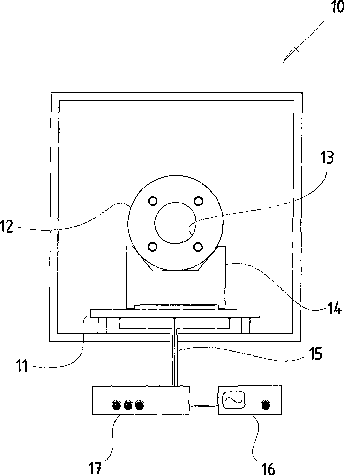
[0103] figure 1 Shown is the front cross-sectional view of the vacuum chamber 10 provided by the present invention, the radio frequency electrode 11 is arranged at the bottom of the chamber, the inner side of the hollow body is to be plated and has an opening 13, and the hollow body is arranged on the radio frequency through an assembly 14 on the electrode.

[0104] The radio frequency electrode 11 inside the vacuum chamber 10 has three lead wires 15 through which a radio frequency voltage generated by a radio frequency generator (RF generator) 16 is fed to the radio frequency electrode 11 . By means of a matching box connected between the adjustable generator 16 and the RF electrode 11, as it is called, the individual leads of the RF electrode 11 can be individually adjusted with the aid of trimmer potentiometers to produce Uniform alternating field of uniform high magnetic field strength.

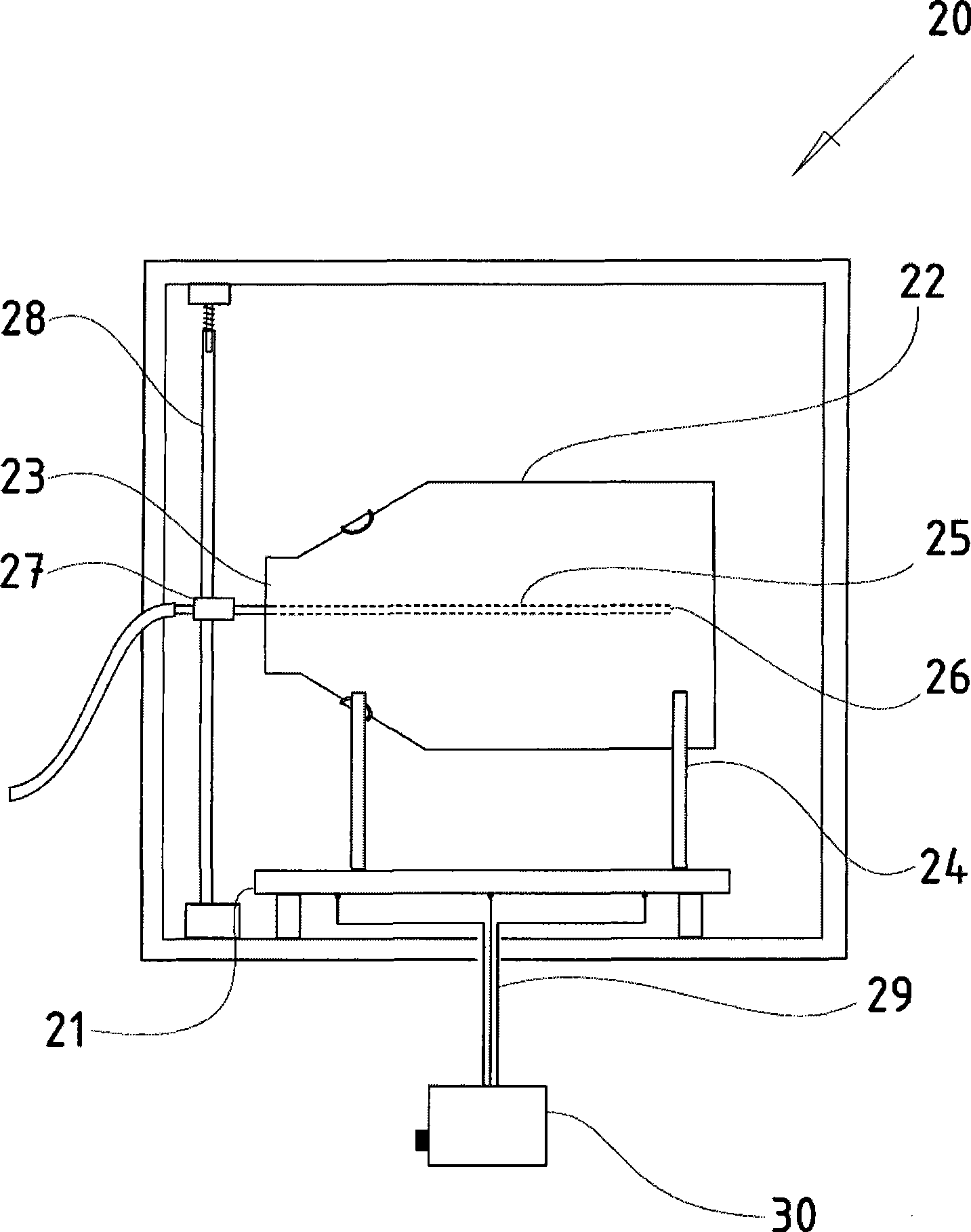
[0105] figure 2 Shown is a side sectional view of the same vacuum chamber 20, wit...


PUM


Abstract

The invention relates to a method for plasma-assisted chemical vapour deposition for coating, or removing material from, the inner wall of a hollow body (42). A gas lance (44) is introduced into the hollow body (42), and a cavity plasma (45) is formed by applying an electrical high-frequency field to a high-frequency electrode (41), forming a plasma cloud arranged on the tip of the gas lance.

Description

【Technical field】 [0001] The invention relates to a method for plasma-assisted chemical vapor deposition for coating or removing material on the inner wall of a hollow body. 【Background technique】 [0002] This method is already known and is known in technical terms as plasma deposition (PECVD, "plasma enhanced chemical vapor deposition") or ion etching, plasma etching. [0003] Based on this, the workpiece is placed in a vacuum chamber and held there. The chamber is evacuated until the pressure of the residual gas is in the high vacuum or ultra-high vacuum region, and injected with inert working gas. Next, the low-pressure plasma is introduced into the RF field through the RF electrodes arranged in the vacuum chamber, so that the low-pressure plasma is ignited. In this case, an ionized gas is introduced which contains a considerable proportion of fast-moving free charge carriers, for example ions or electrons. [0004] In PECVD, a gas called a reactant gas is fed into th...

Claims


Application Information

Patent Timeline
Patent Type & Authority Applications(China)
IPC IPC(8): C23C16/04
CPCC23C16/045H01J37/32366C23C16/509Y10T428/13C23C16/513H01L21/0262
Inventor 奥利弗·诺尔
Owner 拉尔夫·斯坦
Why Eureka
Try Eureka