X-ray tube with ion deflecting and collecting device made from a getter material

A technology of X-ray tube and getter material, applied in medical X-ray imaging system and medical X-ray imaging field, can solve the problems of reducing the service life and damaging the structure of the transmitter, and achieves the realization of temperature increase, low manufacturing cost, overall simple structure

Inactive Publication Date: 2009-09-02
KONINKLIJKE PHILIPS ELECTRONICS NV
View PDF3 Cites 8 Cited by
  • Summary
  • Abstract
  • Description
  • Claims
  • Application Information

AI Technical Summary

Problems solved by technology

This can damage the emitter structure and thus reduce the ser

Method used


Image

  • X-ray tube with ion deflecting and collecting device made from a getter material
  • X-ray tube with ion deflecting and collecting device made from a getter material
  • X-ray tube with ion deflecting and collecting device made from a getter material

Examples


Embodiment Construction

[0068] The illustrations in the figures are schematic. It should be noted that in different figures, similar or identical elements have the same reference signs or reference signs differing only in the first digit compared to the corresponding reference signs.

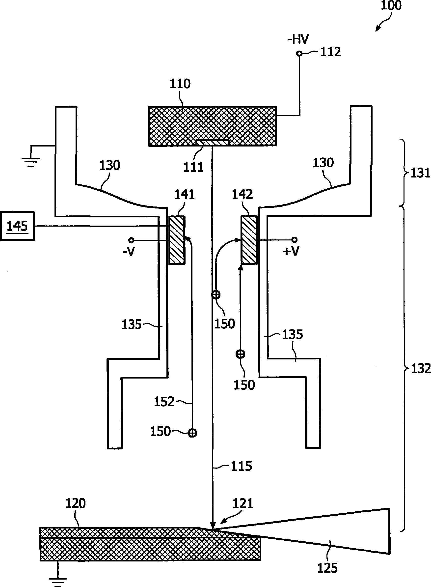
[0069] figure 1A cross-sectional view of the X-ray tube 100 is shown. X-ray tube 100 includes an electron source 110 with an electron emitter 111 . When heated, the electron emitters 111 are capable of releasing electrons projected along the beam path 115 . For clarity, in figure 1 Beam optics like a Wehnelt cylinder are not shown.

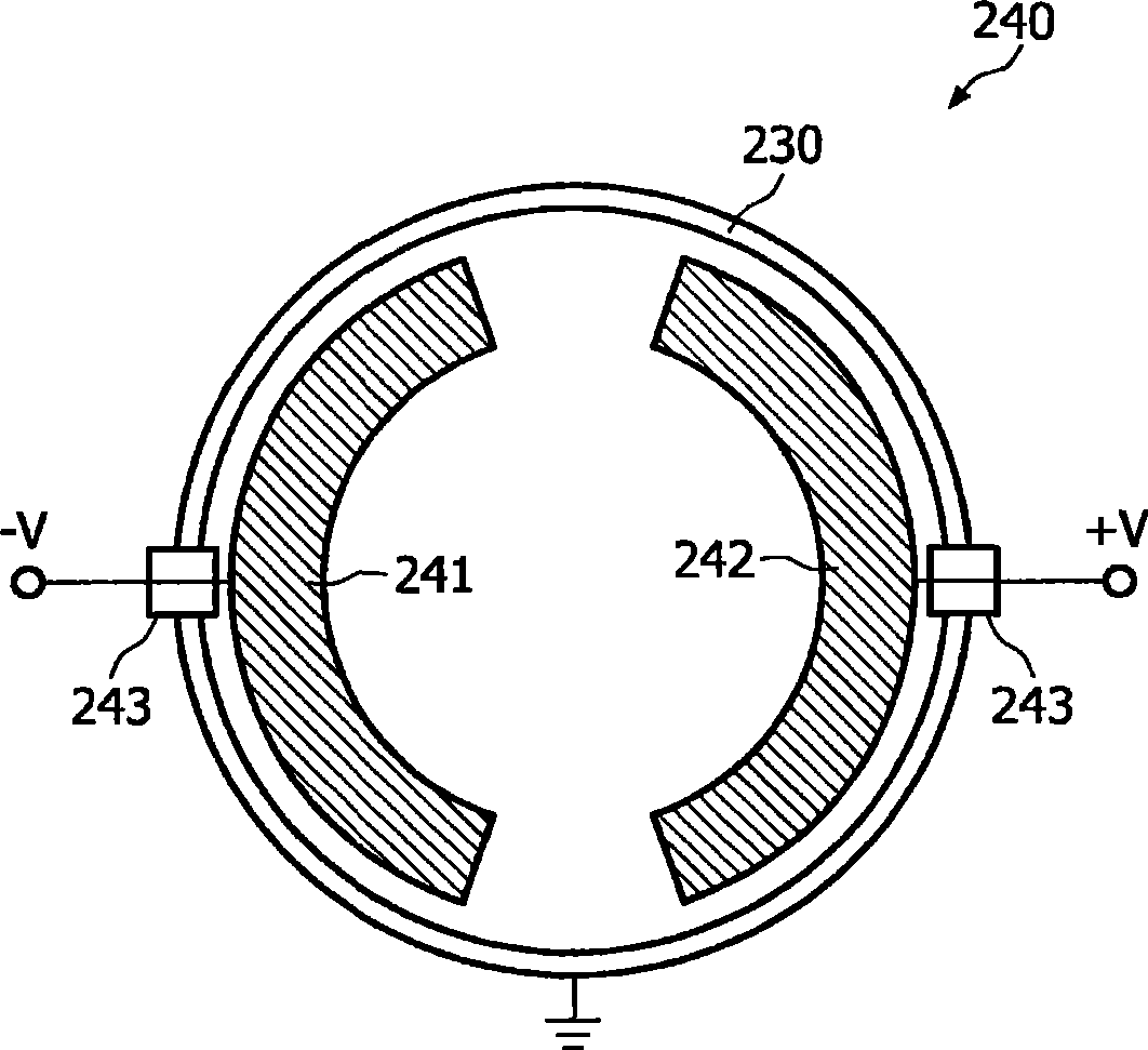
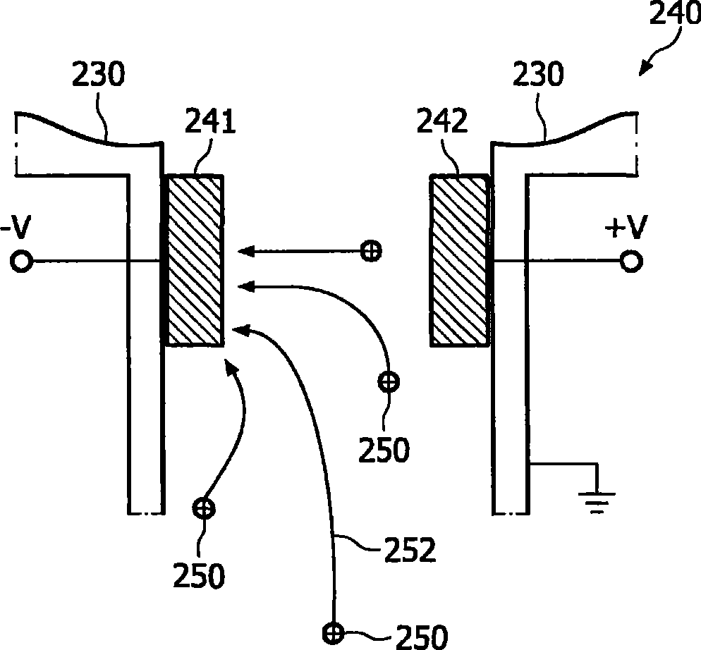
[0070] X-ray tube 100 also includes a high voltage power supply 112 connected to electron source 110 . The high voltage power supply supplies power to the electron source 110 with a negative high voltage -HV. The field electrode 130 is arranged between the electron source 110 and the target anode 120 . According to the embodiment described here, the field electrodes 130 are tubula...


PUM


Abstract

The invention describes an X-ray tube (100) comprising an ion manipulation arrangement (140) having at least one ion collector electrode (141). The ion collector electrode (141) is made at least partially from a getter material. The ion manipulation arrangement (140) is in particular beneficial for high-end X-ray-tubes including an electrical field-free region (131). The ion manipulation arrangement (140) produces an electrical field, which deflects ions (150). When impinging onto the getter electrode (141) the ions (150) are permanently collected and thus removed from the interior of an evacuated envelope of the X-ray tube (100). This avoids ion bombardment on an electron emitter (111) of the X-ray tube (100). Additionally the arcing rate caused by residual gas can be reduced significantly. A heating of the getter material may be realized with heating wires or by a defined bombardment of scattered electrons (322) onto the electrodes (341, 342) comprising the getter material.

Description

technical field [0001] The invention relates to the field of generating X-rays by means of X-ray tubes. In particular, the invention relates to an X-ray tube comprising ion treatment means adapted to collect residual particles present in an evacuated envelope of the X-ray tube. [0002] The invention further relates to an X-ray system, in particular a medical X-ray imaging system, wherein the X-ray system comprises an X-ray tube as described above. [0003] Furthermore, the invention relates to a method for generating X-rays, in particular for medical X-ray imaging. The X-rays are generated by means of an X-ray tube as described above. Background technique [0004] High-end and future X-ray tubes need to be able to provide variable focus shape, focus size and focus position. Compared to conventional X-ray tubes, these tubes have a greater distance between the cathode representing the electron source and the target anode on which the focal point is created. [0005] Figu...

Claims


Application Information

Patent Timeline
IPC IPC(8): H01J35/04H01J35/20H01H1/48H01J3/26H01J7/18
CPCH01J41/12H01J35/20H01J2235/205H01J35/04H01J7/18
Inventor S·胡特曼
Owner KONINKLIJKE PHILIPS ELECTRONICS NV
Why Eureka
Try Eureka