Check patentability & draft patents in minutes with Patsnap Eureka AI!

Rotor assembly for use in line start permanent magnet synchronous motor

A technology of components and rotors, applied in the direction of electric components, asynchronous induction motors, synchronous machines, etc., can solve the problems of reducing efficiency, torque ripple, noise, etc., and achieve the effect of reducing torque ripple phenomenon

Inactive Publication Date: 2009-09-02
DAEWOO ELECTRONICS CO LTD
View PDF0 Cites 7 Cited by
  • Summary
  • Abstract
  • Description
  • Claims
  • Application Information

AI Technical Summary

Problems solved by technology

[0011] However, when the polarity of the magnetic flux is switched in the conventional LSPM synchronous motor 10 according to the prior art, that is, when the figure 2 When the polarity of the permanent magnet 13d is switched in the part "a" shown, a torque ripple phenomenon generally occurs, wherein figure 2 shows the secondary voltage induced in the rotor 13 depending on the rotation angle of the rotor 13
This torque ripple phenomenon causes the rotor 13 to vibrate, which may generate noise and thus reduce efficiency

Method used


Image

  • Rotor assembly for use in line start permanent magnet synchronous motor
  • Rotor assembly for use in line start permanent magnet synchronous motor
  • Rotor assembly for use in line start permanent magnet synchronous motor

Examples


Embodiment Construction

[0027] Hereinafter, preferred embodiments of the present invention will be described in detail with reference to the accompanying drawings so that those skilled in the art can easily implement the present invention. However, it should be appreciated that the present invention is not limited to the preferred embodiments, and may be varied in various ways.

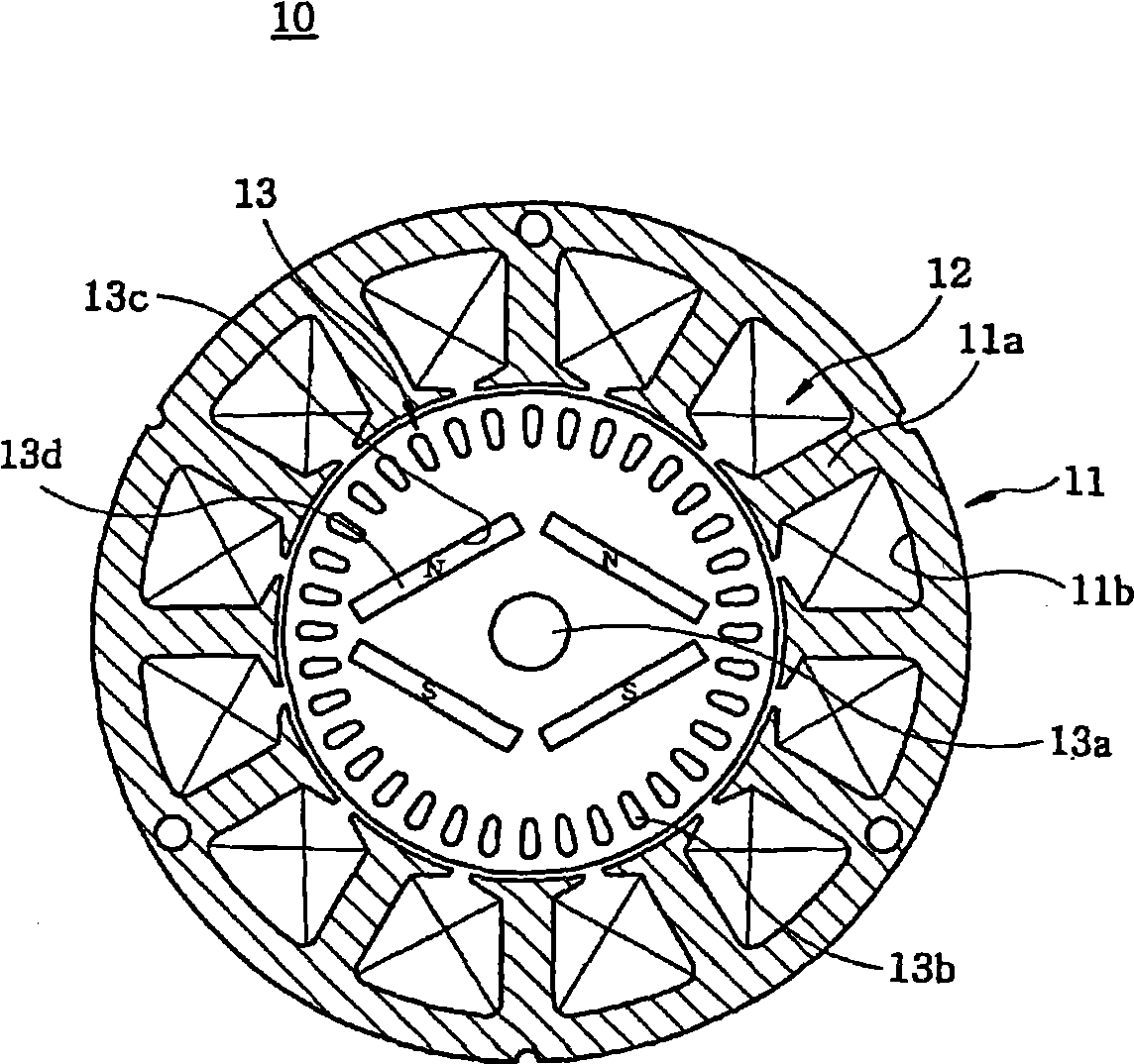
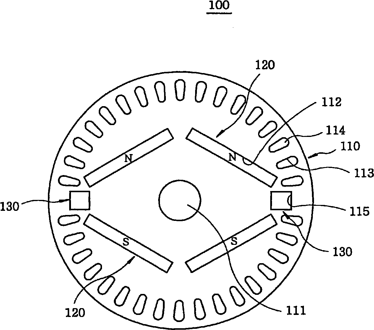
[0028] refer to image 3 , provides a plan view showing a rotor for a line-start permanent magnet (LSPM) synchronous motor according to a first embodiment of the present invention. Such as image 3 As shown, the rotor assembly 100 used in the LSPM synchronous motor according to the first embodiment of the present invention is installed inside the stator 11 (see figure 1 ), a gap is configured between the rotor assembly 100 and the stator 11 so that the rotor assembly 100 can rotate in the stator 11.

[0029] The rotor assembly 100 includes a rotor core 110, a plurality of permanent magnets 120 and a pair of pulsation supp...


PUM


Abstract

A rotor assembly includes a rotor core which has a central portion and a circumferential portion, wherein a shaft hole is formed at the central portion, and a plurality of conductors are arranged along the circumferential portion; a multiplicity of permanent magnets provided at a portion of the rotor core around the shaft hole; and at least one first ripple-reduction conductor formed at a polar switchover region of the rotor core, the polar switchover region being positioned between two opposite poles of two adjacent permanent magnets, so that a polar switchover of an induction voltage induced in the rotor core is alleviated to reduce a torque ripple phenomenon.

Description

technical field [0001] The present invention relates to a rotor for a line-start permanent magnet (LSPM) synchronous motor; and more particularly, to a rotor used in an LSPM synchronous motor capable of preventing torque ripple phenomenon during operation of the LSPM synchronous motor. Background technique [0002] In general, an electric motor is a device that converts electrical energy into mechanical energy to obtain rotational power, and it is widely used in industrial equipment and home appliances. Motors are roughly classified into alternating current (AC) motors and direct current (DC) motors. [0003] Meanwhile, the LSPM synchronous motor (i.e., a type of AC motor) is driven by the torque generated by the interaction between the secondary current generated by the voltage induced on the conductors in the rotor and the magnetic flux generated by the winding wires of the stator of. At this point, the torque starts from the resultant torque of the reluctance torque and...

Claims


Application Information

Patent Timeline
Patent Type & Authority Applications(China)
IPC IPC(8): H02K17/26H02K17/02
CPCH02K1/223H02K1/276H02K17/165H02K21/46H02K17/20H02K15/03
Inventor 申滥澈
Owner DAEWOO ELECTRONICS CO LTD
Features
  • R&D
  • Intellectual Property
  • Life Sciences
  • Materials
  • Tech Scout
  • Unparalleled Data Quality
  • Higher Quality Content
  • 60% Fewer Hallucinations
Learn More