
Cast-in-situ hollow floor for storing and recycling heat energy

A hollow floor and cast-in-place technology, which is applied in the direction of floor slabs, building thermal performance improvement, sustainable buildings, etc., can solve the problems of high energy consumption, low comprehensive utilization level of cast-in-place hollow floors, and inflexible systems, achieving The effect of maintaining stability and improving the effect of earthquake resistance and crack prevention

Inactive Publication Date: 2011-03-23
HUNAN BDF ENERGY SAVING TECH
View PDF2 Cites 0 Cited by
  • Summary
  • Abstract
  • Description
  • Claims
  • Application Information

AI Technical Summary

Problems solved by technology

[0005] In order to solve the lack of central heating in most areas and realize low-energy automatic heating in civil buildings and rural peasant houses, overcome the high energy consumption of existing heating technology and the inflexibility of the system, floor heating still occupies more than 100 mm of floor space, and cast-in-place empty stomach The level of comprehensive utilization of the floor is not high, and the inner wall of the product is not clean. The present invention provides a cast-in-place hollow floor with high strength, simple process, reasonable structure, light weight, energy storage and energy circulation.

Method used


Image

  • Cast-in-situ hollow floor for storing and recycling heat energy
  • Cast-in-situ hollow floor for storing and recycling heat energy
  • Cast-in-situ hollow floor for storing and recycling heat energy

Examples


Embodiment Construction

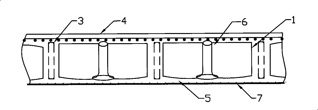
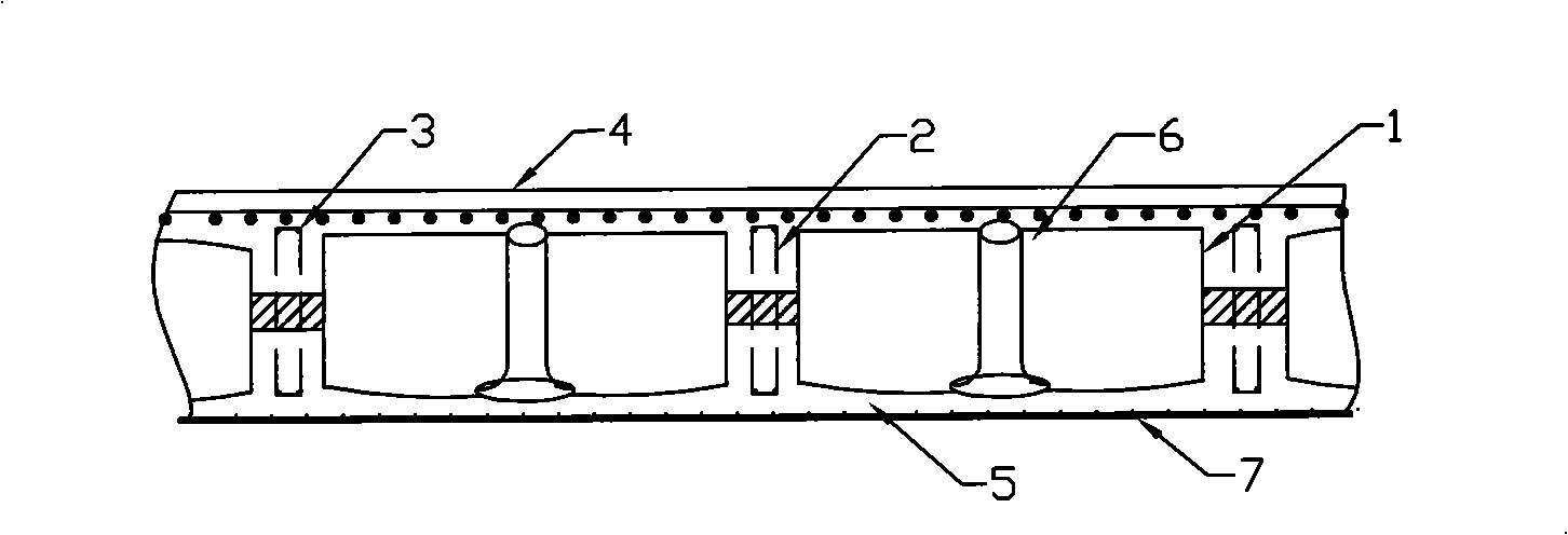
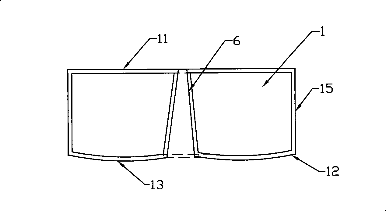
[0024] Such as figure 1 As shown, in the patent documents previously applied by the applicant, a floor structure was introduced, including a thin-walled box 1 in the middle, an upper flange plate 4, rib beams 3, a lower flange plate 5 and a floor template 7 , there are multiple thin-walled boxes and they are cast-in-place with composite cement slurry or assembled from plates. The bottom plate 12 of the thin-walled box 1 has arc-shaped protrusions 13, and the height of the arc-shaped protrusions 13 is ≤19 mm. The outer surface of the bottom plate There are at least three arc-shaped protrusions 13, and the bottom plate 12 of the thin-walled box body 1 and the top cover 11 have opposite lower holes and upper holes, and the lower holes on the bottom plate are connected with the upper holes on the top cover through a closed through passage 6 , the present invention will be further described below in conjunction with accompanying drawing.

[0025] The thin-walled box used in this s...


PUM


Abstract

The invention relates to a cast-in-situ hollow floor for storing and recycling heat energy and a preparation method thereof, adopting the following scheme based on the prior hollow floor: each box and thin wall in the floor is communicated with each other from side faces by connective channels, so that the box and thin wall of the each floor of a whole building is communicated with each other so as to be formed as a storable and recyclable inner passage which is internally filled with hot gas to provide heat energy for the whole building. The scheme uses the characteristics of light weight and strong earthquake resistance of the prior hollow floor so as to completely use the upper face and the lower face of the floor, thereby overcoming the defect that the geotherm only can be radiated from upper side; the scheme can adopt modes such as parallel connection, series connection or multiple series, and the like, for the box and thin wall of the hollow floor, so that the required temperature in the hollow floor comes up to the required standard in a faster and more reasonable way, as well as circulation is more convenient; and the scheme also can adopt a separate control method so as to lead the inner passage of the floor of each floor and each room to be circulated or closed.

Description

technical field [0001] The invention relates to an energy-saving building, in particular to a cast-in-place hollow floor capable of storing hot air and circulating hot air. Background technique [0002] At present, most of the buildings with brick-concrete structure and frame structure use prefabricated hollow slabs as floor slabs. This kind of floor slab can be constructed quickly and has the advantages of low cost, but because there is no firm connection between two adjacent prefabricated hollow slabs , Only cement mortar is used to fill the joints, so the integrity is poor, which is not conducive to earthquake resistance, and cracks and water seepage often occur. There are also some cast-in-place concrete floor technology, using the prepared formwork components and reinforced concrete to mix together to make the floor, but there are still problems such as uneven bottom surface of the floor and heavy formwork. [0003] Heating in northern my country uses pipeline heat or ...

Claims


Application Information

Patent Timeline
Patent Type & Authority Patents(China)
IPC IPC(8): E04B5/48
CPCY02B80/40Y02A30/24Y02B80/00
Inventor 王本淼韩爱兴王海崴程志军
Owner HUNAN BDF ENERGY SAVING TECH
Learn More