Combined screw impeller wind power generation system

A technology of wind power generation system and helical impeller, which is applied in wind turbine components, wind energy power generation, wind turbines, etc., can solve the problems of difficulty in processing and manufacturing, and achieve the effects of increasing rotational torque, reducing starting inertia, and reducing frictional resistance.

Active Publication Date: 2009-09-09
江苏易佳节能科技有限公司
View PDF0 Cites 19 Cited by
  • Summary
  • Abstract
  • Description
  • Claims
  • Application Information

AI Technical Summary

Problems solved by technology

In recent years, vertical-axis wind power generation equipment has generally received attention. However, to reach the megawatt level, the manufacture of wind blades for vertical-axis wind power generation equipment has always been a major problem in the industry, because the megawatt-level vertical axis wind power generation equipment Wind blades have both shape requirements and scale requirements. It is very difficult to manufacture the specified shape of wind blades under such large-scale requirements. It can even be said that it is almost impossible.

Method used


Image

  • Combined screw impeller wind power generation system
  • Combined screw impeller wind power generation system
  • Combined screw impeller wind power generation system

Examples


Embodiment 1

[0036] Embodiment 1: This embodiment is a large-scale wind power generation system, its composition and structure are as follows Figure 14 shown.

[0037] This embodiment shows that the wind power generation system is composed of the following parts: helical impeller, transmission mechanism, multiple generator sets, magnetic suspension bearing, wind speed and direction instrument, power storage device and control device.

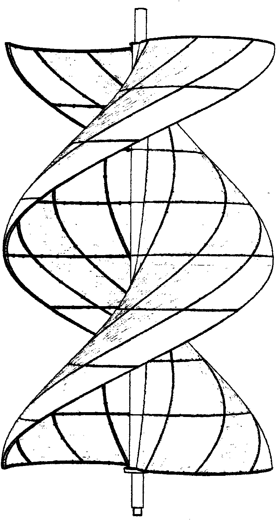
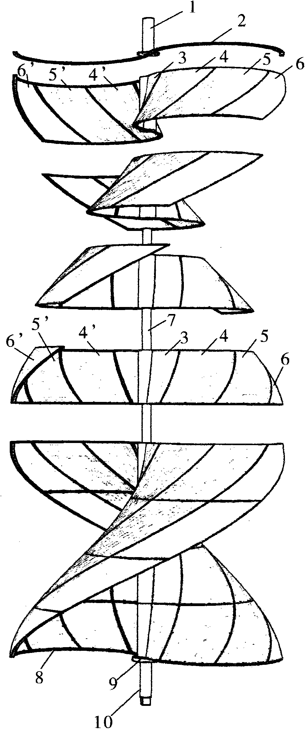
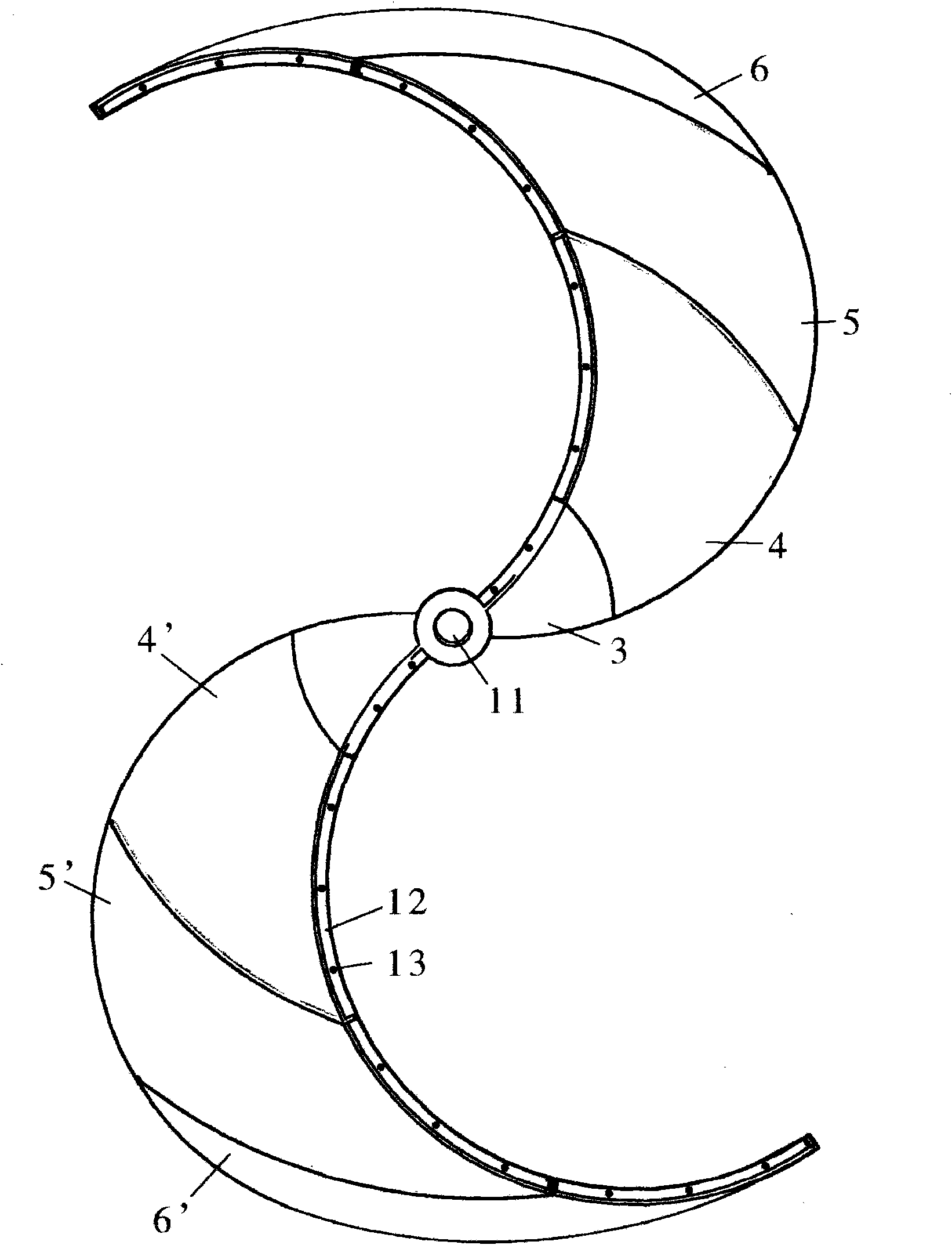
[0038] The structure of the spiral impeller in this embodiment is as follows: figure 1 , 2 , 3, 4, 5, 6, 7, 8, 9. The helical impeller is composed of impeller upper shaft pin 1, impeller upper end S piece, central shaft member 3, middle I member 4, middle II member 5, edge member 6, impeller center shaft 7, impeller lower end S piece, impeller lower shaft pin 9 Composition, the central axis member 3 is located at the central axis position, the middle I member 4, the middle II member 5 and the edge member 6 are radially and symmetrically arranged on both ...

Embodiment 2

[0043] The structure of this embodiment is as follows Figure 18 shown.

[0044] This embodiment provides a small-sized spiral impeller wind power generation device, which can be used for street lighting. The device is fixed to a street light pole 55 through an upper beam 48 and a lower beam 54 . This device transmission annular gear 51, transmission gear 50 and three generator sets 49 are all arranged on the helical impeller directly above, and transmission gear 50 is fixed with the generator rotor shaft.

[0045] Due to the relatively small size of the helical impeller in this embodiment, one central shaft member, two intermediate members, and two edge members can be used to assemble and combine. In this way, the helical impeller can be realized only by making molds for three sub-components. If the diameter of the helical impeller is even smaller, the helical impeller can also be molded axially in sections, so that only one pair of molds is needed to realize the helical imp...

Embodiment 3

[0048] This embodiment provides a small independent spiral impeller wind power generation device, the composition and structure of the device are as follows Figure 19 shown.

[0049] In this embodiment, the support frame base 61 is fixed by the support frame fastening steel cable, the helical impeller 58 is fixed on the annular gear 59, and the rotor shafts of the three generator sets 60 are meshed with the annular gear through transmission gears. The manufacturing method of the spiral impeller of this embodiment is the same as that of Embodiment 2.

[0050] This embodiment is more suitable to be installed at the tuyere with steep terrain.


PUM


Abstract

The invention relates to a screw impeller wind power generation system, which is mainly characterized in that a screw impeller is formed by assembling a plurality of vertical impeller members along the axial direction, each vertical impeller member is formed by splicing and assembling a plurality of horizontal impeller members along the radial direction of the screw impeller at the same time, the screw impeller is linked with a plurality of generating units through a transmission mechanism, and the generating units output electric energy in a parallel connection mode, thereby being favorable for the after-treatment of the output electric energy, and improving the quality of the supplied electric energy. A clutch device is arranged between the generating units and the transmission mechanism, and a control device receives a wind velocity and wind direction treatment electric signal and performs real-time control of the disengagement or engagement between the single generating unit and the transmission mechanism according to a preset program further to change starting and operation loads of the screw impeller. In addition, the adoption of magnetic suspension bearings can overcome the partial gravitational force born by the impeller, and can also reduce the friction resistance between the impeller and other components further to reduce the lowest starting wind velocity of the impeller and improve the wind-electricity conversion efficiency. The wind power generation system greatly reduces manufacturing, transportation, installation, maintenance, and series costs.

Description

technical field [0001] The invention relates to a wind power generating equipment, in particular to a super large wind power generating equipment. Background technique [0002] For large-scale wind power generation equipment, especially megawatt-level wind power generation equipment, if traditional horizontal-axis paddle blades are used, the length of a single blade should reach 50 meters to 70 meters. Production, transportation, installation, etc. will encounter difficulties. In recent years, vertical-axis wind power generation equipment has generally received attention. However, to reach the megawatt level, the manufacture of wind blades for vertical-axis wind power generation equipment has always been a major problem in the industry, because the megawatt-level vertical axis wind power generation equipment Fan blades have both shape requirements and scale requirements. It is very difficult to manufacture the specified fan blade shape under such a large-scale requirement, ...

Claims


Application Information

Patent Timeline
Patent Type & Authority Applications(China)
IPC IPC(8): F03D3/06F03D9/00F03D7/06F03D11/00F16C32/04F03D9/25F03D80/70
CPCY02E10/728Y02E10/74Y02P70/50
Inventor 胡国祥严楼
Owner 江苏易佳节能科技有限公司
Why Eureka
Try Eureka