Weighting sensor with intensity demodulation chirped fiber grating
A weighing sensor and chirped grating technology, applied in the field of fiber grating sensors, to achieve the effects of low equipment cost, high weighing accuracy and good repeatability
- Summary
- Abstract
- Description
- Claims
- Application Information
AI Technical Summary
Problems solved by technology
Method used
Image
Examples
Embodiment Construction
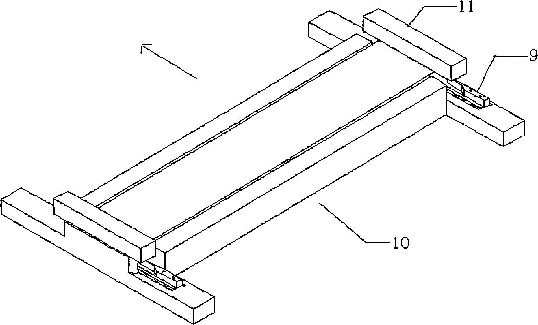
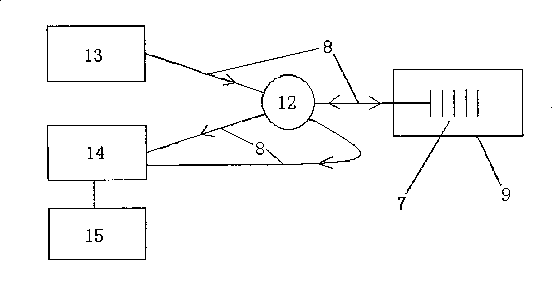
[0026] The following is attached figure 1 , 2 , 3, 4 further describe the technical solution of the present invention.
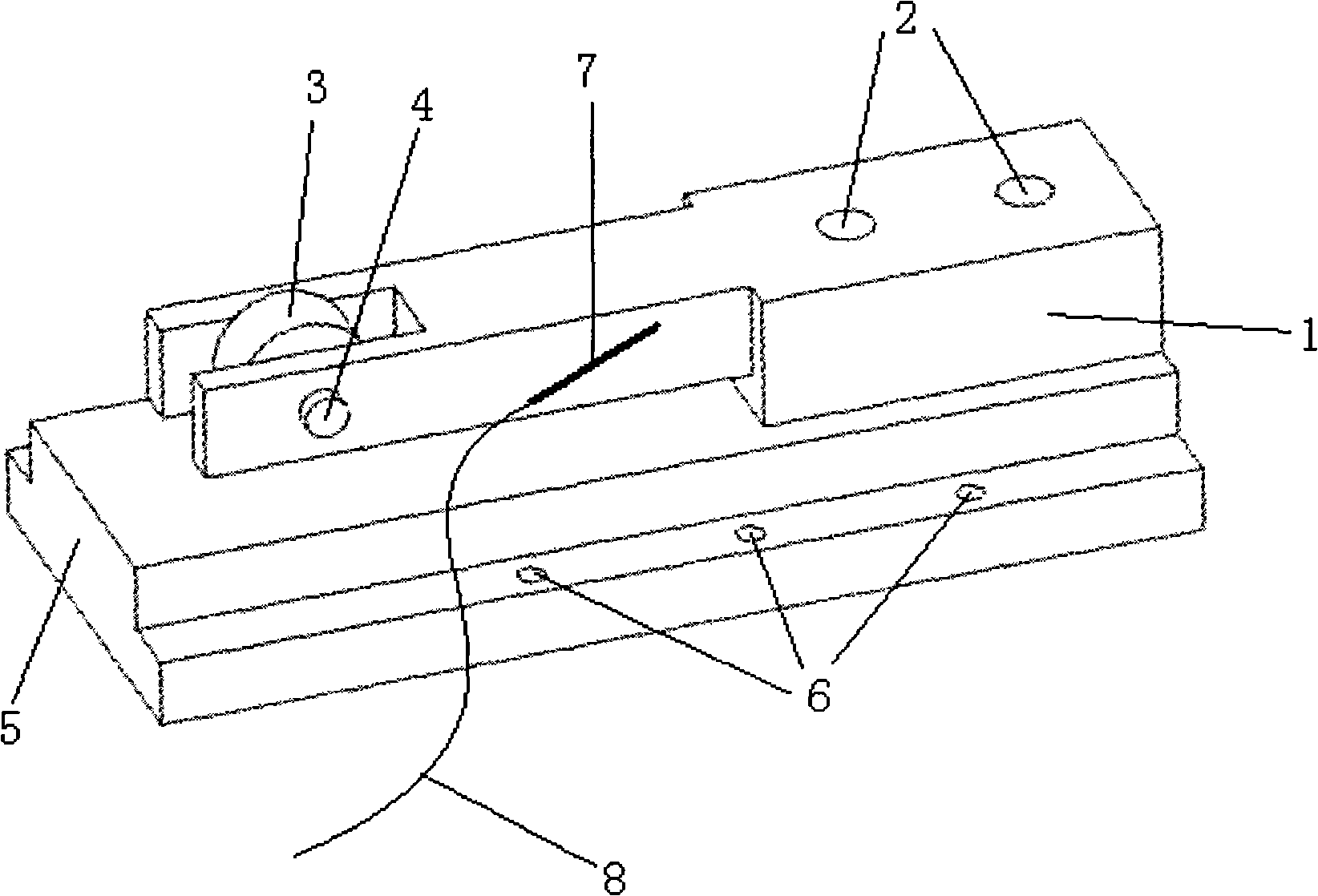
[0027] The structural schematic diagram of the optical fiber chirped grating load cell of the present invention is as follows figure 1 shown. The sensor adopts a cantilever beam 1 structure, and the cantilever beam 1 is fixed on the sensor base 5 through screw holes 2 . A bearing 3 is installed at the free end of the cantilever beam, and the bearing 3 is installed on the free end of the cantilever beam 1 through a bolt 4 . The sensing fiber grating 7 is pasted on the side of the cantilever with an inclination of 5-45 degrees. Since the sensor is used for vehicle weighing, the material of the cantilever beam 1 and other components is preferably steel with a relatively large Young's modulus to prevent the fiber chirped grating 7 from being damaged due to excessive strain.
[0028] When in use, the fiber optic chirped grating load cell 9 is fixed on the fr...
PUM
 Abstract
Description
Claims
Application Information
 - R&D
- Intellectual Property
- Life Sciences
- Materials
- Tech Scout
- Unparalleled Data Quality
- Higher Quality Content
- 60% Fewer Hallucinations
Browse by: Latest US Patents, China's latest patents, Technical Efficacy Thesaurus, Application Domain, Technology Topic, Popular Technical Reports.
© 2025 PatSnap. All rights reserved.Legal|Privacy policy|Modern Slavery Act Transparency Statement|Sitemap|About US| Contact US: help@patsnap.com


