Isolating switch with quick break function

A technology for isolating switches and conductive parts, which is applied in the field of switches and can solve problems such as rising product costs, inappropriate installation, and easy-to-ablate contacts

Inactive Publication Date: 2009-09-09
浙江开关厂有限公司
View PDF0 Cites 14 Cited by
  • Summary
  • Abstract
  • Description
  • Claims
  • Application Information

AI Technical Summary

Problems solved by technology

The problems of the above isolating switch are: using conventional electric or manual mechanism, the opening and closing speed is slow, the arcing time is long when the current is opened and closed, and there is no arc extinguishing device inside the switch, which is easy to ablate the contacts. Especially GIS (SF 6 Fully-enclosed combination electrical appliances) The busbar isolating switch in the equipment will produce metal spatter when the busbar is opened and closed to convert current and arc, resulting in serious pollution on the surface of the insulator, which directly affects the internal insulation performance of GIS
[0007] After taking the above improvement measures, although the ability of the disconnector to open and close the busbar to convert current can be significantly improved, the problem is that the structure of the operating mechanism and the switch body is more complicated or the production process of the dynamic and static contacts is more difficult. , leading to an increase in product cost
For GIS products, due to the small size of GIS products, compact layout, and short connecting busbars, these isolating switches with overly complicated structures are not suitable for installation in GIS products.

Method used


Image

  • Isolating switch with quick break function
  • Isolating switch with quick break function

Examples


Embodiment 1

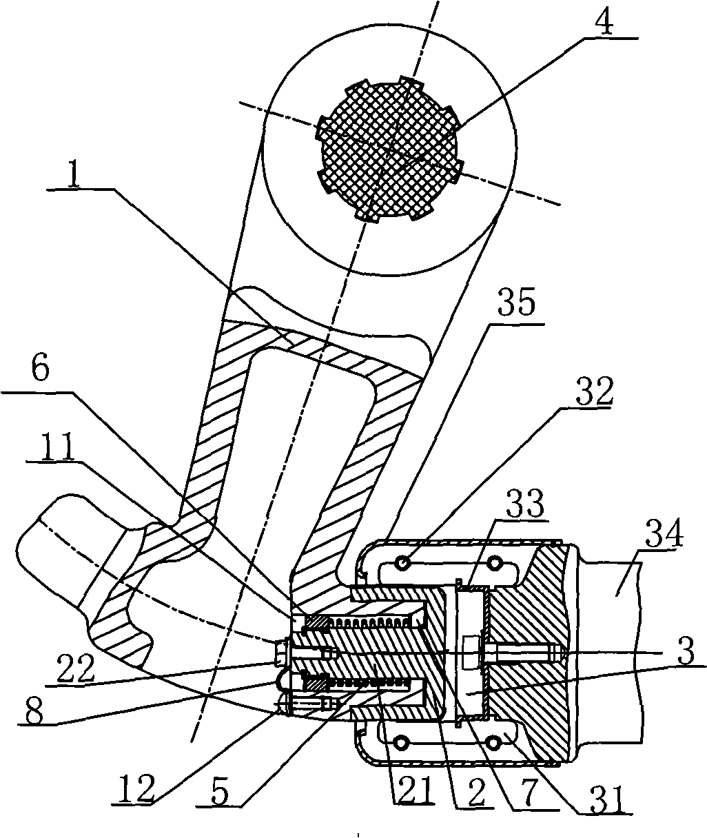
[0020] Such as figure 1 As shown, an isolating switch with a quick split function includes a moving contact 1, a quick split moving contact 2, a static contact 3, and an insulating rotating shaft 4 that controls the movement of the moving contact 1. The static contact 3 includes a static contact base 35, a cage 33, a static contact finger 31 and a tension spring 32. The static contact finger 31 is connected to the static contact base 34, and the static contact finger 31 is surrounded by a tension spring. 32. A shield 35 is provided on the outer surface of the static contact 3.

[0021] The fast moving contact 2 is a cup body with an axial column 21, and the closed end of the cup body is inserted into the static contact 3. The other end of the quick transfer contact 2 is sleeved with the front end of the moving contact 1. The front end of the moving contact 1 is provided with a cylindrical cavity 11, and the front end of the cylindrical cavity 11 is provided with a retaining ring ...

Embodiment 2

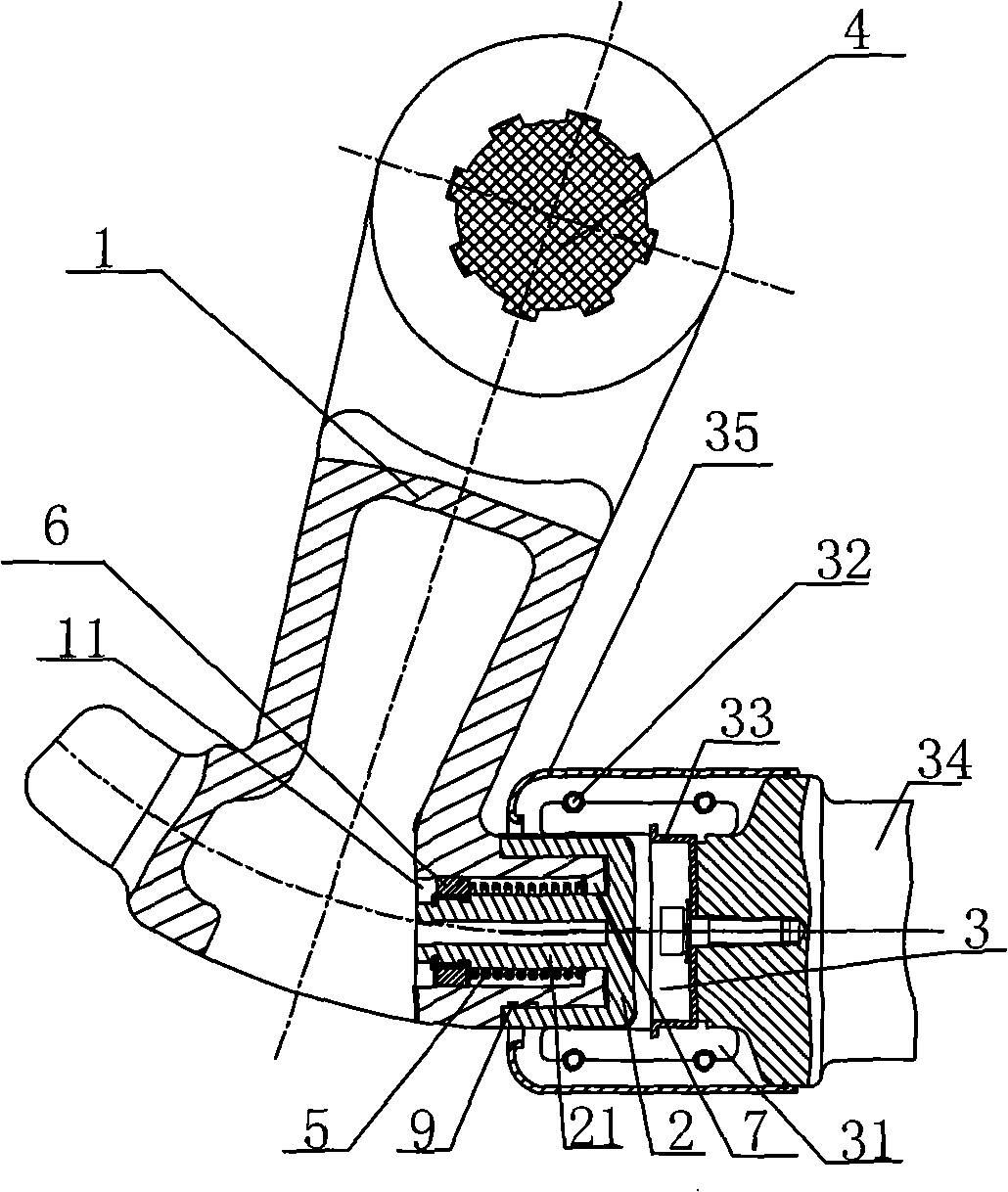
[0024] Such as figure 2 As shown, an isolating switch with a quick split function includes a moving contact 1, a quick split moving contact 2, a static contact 3, and an insulating rotating shaft 4 that controls the movement of the moving contact 1. The static contact 3 includes a static contact seat 34, a holder 33, a static contact finger 31, and a tension spring 32. The static contact finger 31 is connected to the static contact seat 34, and a tension spring surrounds the circumference of the static contact finger 31 32. A shield 35 is provided on the outer surface of the static contact 3.

[0025] The fast moving contact 2 is a cup body with an axial column 21, and the closed end of the cup body is inserted into the static contact 3. The other end of the quick transfer contact 2 is sleeved with the front end of the moving contact 1. The front end of the moving contact 1 is provided with a cavity 11, and the front end of the cylindrical cavity 11 is provided with a retaining ri...


PUM


Abstract

The invention relates to an isolating switch with quick break function, comprising a moving contact, an operating mechanism which controls the moving contact to move and a fixed contact corresponding to the moving contact. The switch is characterized in that the switch further comprises a quick break moving contact, one side of which is sheathed in the moving contact, the other side of which is closely contacted with a conductive part of the fixed contact, a spring is arranged between the quick break moving contact and the moving contact, the quick moving contact is electrically connected with the moving contact. The isolating switch features short-time generation of voltaic arc when separating brake is carried out on the isolating switch, thus ensuring that the contact is not prone to be burnt by the voltaic arc.

Description

Technical field [0001] The invention relates to a switch, in particular to an isolating switch with a quick split function. Background technique [0002] Isolating switch is an important component in the power system. The main function of ordinary isolating switch is to isolate the circuit and establish isolation and insulation fracture. Special isolating switch is used for the rated voltage of 72.5kV and above in double bus wiring and bypass wiring. In addition to realizing the above basic functions, the bus isolation switch must also be used to switch the circuit, which inevitably requires switching the bus to switch current (commonly known as circulating current). The problems of the above isolation switches are: using conventional electric operation or manual mechanism, the opening and closing speed is slow, the arc time is longer when opening and closing current, there is no arc extinguishing device inside the switch, and the contact is easy to ablate. Especially GIS (SF 6 F...

Claims


Application Information

Patent Timeline
Patent Type & Authority Applications(China)
IPC IPC(8): H01H31/02H01H5/06H01H9/30
Inventor 俞慧忠陈伯荣周庆清宁茂亮苏伟民
Owner 浙江开关厂有限公司
Why Eureka
Try Eureka