

Fiber grating pressure sensor free from temperature influence
A technology of pressure sensor and optical fiber grating, which is applied in the field of sensors, can solve problems such as temperature and pressure cross-sensitivity, and achieve the effects of large measurement range, easy process, and simple structure
- Summary
- Abstract
- Description
- Claims
- Application Information
AI Technical Summary
Problems solved by technology
Method used
Image

Examples
Embodiment 1
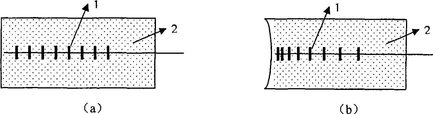
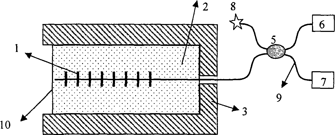
[0020] Embodiment 1: see attached image 3 , the fiber grating adopts a fiber Bragg grating 1, and the fiber Bragg grating 1 is packaged in a metal tubular housing 3 with one end open, and one end of the fiber grating 1 is passed through a small hole in the center of the unopened end face of the tubular housing 3 and connected to a single-mode optical fiber 9 It is connected with 2×2 3dB fiber optic coupler 5; there are four ports on both sides of the fiber coupler 5, and the other port on the side connected to the fiber coupler 5 is connected to the optical fiber refractive index matching solution 8 through a single-mode fiber 9 Middle; two ports on the other side of the fiber coupler 5, one end is connected to the broadband light source 6 through a single-mode fiber 9, and the other end is connected to the demodulation system 7 through a single-mode fiber 9; the fiber grating 1 is packaged by filling the polymer acrylate 2 in Tubular housing 3.
[0021] The assembly steps a...
Embodiment 2
[0022] Embodiment 2: see attached Figure 4 , the structural diagram of the fiber grating pressure sensor using packaging method 2. The packaging steps are as follows: (1) process the alloy tubular housing 4 and the protective back cover 11 so that the two can be connected by sealing threads, and the inner wall of the tubular housing 4 is also ground into a rough surface; (2) remove the fiber Bragg grating 1 package Part of the coating layer; (3) placing the fiber grating 1 on the central axis of the tubular housing 4 and pre-stretching it, and then encapsulating the prepared polymer polyurethane 2 in the tubular housing 4; (4) placing A protective back cover 11 is added to the tubular casing 4, and the encapsulated polymer 2 is cured for calibration measurements. Its measurement method and image 3 Same as shown.
[0023] Compare image 3 shown in Example 1 and Figure 4 From the shown embodiment 2, it can be concluded that the main difference between the two lies in the...
PUM
 Abstract
Description
Claims
Application Information