A luminous module encapsulation method

A light-emitting module and packaging method technology, which is applied in the direction of electrical components, electrical solid devices, circuits, etc., can solve the problems of difficult control of white light uniformity and poor yield rate, and achieve the effect of avoiding yellow halo phenomenon and simple and fast manufacturing process

Active Publication Date: 2009-09-16
AU OPTRONICS CORP
View PDF0 Cites 16 Cited by
  • Summary
  • Abstract
  • Description
  • Claims
  • Application Information

AI Technical Summary

Problems solved by technology

[0006] The invention provides a packaging method of a light-emitting module, which is used to avoid the problem that the uniformity of the white light emitted by the formed white light-emitting diode is not easy to control and the yield rate is not good due to the inability to uniformly distribute the phosphor powder

Method used


Image

  • A luminous module encapsulation method
  • A luminous module encapsulation method
  • A luminous module encapsulation method

Examples


Embodiment Construction

[0045] " Figure 1A "," Figure 1B "," Figure 1C "," Figure 1D "," Figure 1E "," Figure 1F "and" Figure 1G ” is a schematic flowchart of the packaging method of the light emitting module according to the first embodiment of the present invention.

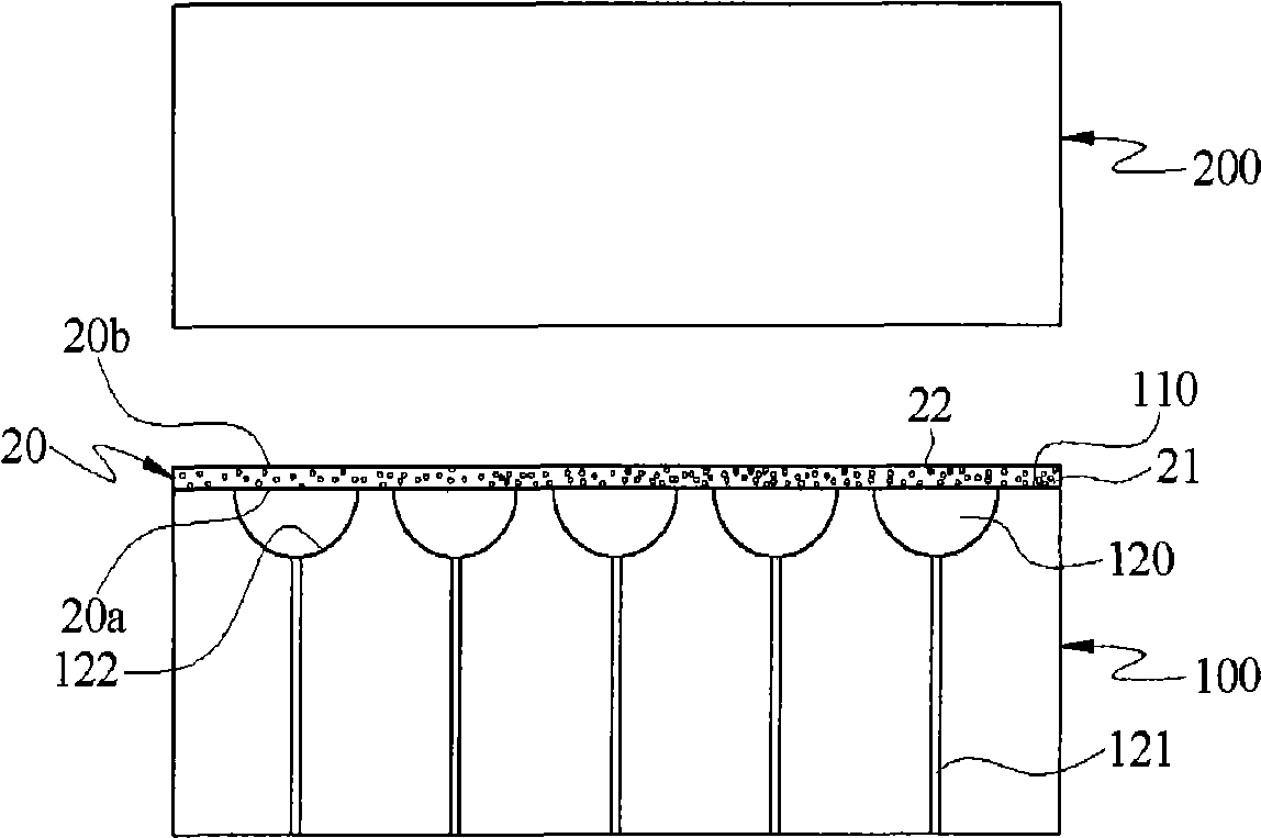
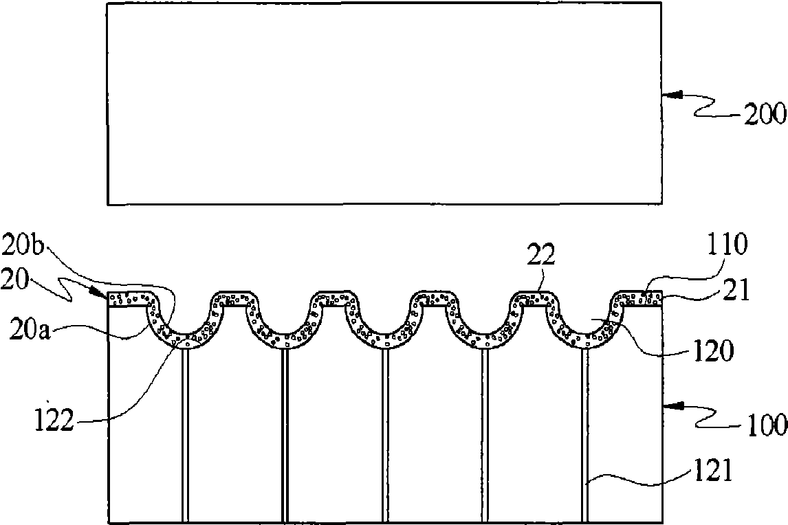
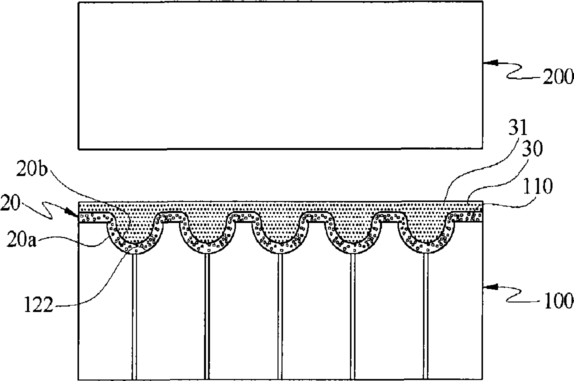
[0046] The packaging method of the light emitting module of this embodiment is applicable to a molding mechanism having an upper mold 100 and a lower mold 200 , wherein the surface 110 of the upper mold 100 has more than one mold cavity 120 .

[0047] The mold cavity 120 is disposed on the surface 110 of the upper mold 100 facing the lower mold 200 . The upper mold 100 also has a plurality of through holes 121 . The through hole 121 is arranged one-to-one with the mold cavity 120 and communicates with the mold cavity 120 .

[0048] Please refer to" Figure 1A ", according to the first embodiment of the packaging method of the light-emitting module of the present invention, first, the fluorescent film 20 is placed on th...


PUM


Abstract

A luminous module encapsulation method is suitable for a compression molding mechanism having an upper mold and a lower mold, wherein, the surface of the upper mold is provided with mold cavity. The encapsulation method includes: firstly arranging the fluorescent film on the surface of the upper mold having the mold cavity; and then, forming the gel on the fluorescent membrane; then, placing the colloid on the substrate, and one side of the substrate having the light emitting chip is contacted with the side of colloid; then, the upper mold and the lower mold performing heat pressing to the substrate, the colloid and the fluorescent film, to form a luminous module with at least one light-emitting component; after the compression, divorcing the luminous module from the upper mold and the lower mold. Herein, fluorescent powders are homogeneously distributed on the light outlet surface of the light-emitting components, which can avoid the heating absorption of the fluorescent powder and can improve the process speed.

Description

【Technical field】 [0001] The invention relates to a packaging method, in particular to a packaging method of a light emitting module. 【Background technique】 [0002] A light emitting diode (Light Emitting Diode, LED) belongs to a compound semiconductor device, which is mainly composed of III-V group elements. Light-emitting diodes have the characteristics of low driving voltage, long life, low power consumption, fast response, and high safety (light-emitting diodes emit cold light and generate relatively little heat). [0003] Most of the current white light emitting diodes are formed by matching ultraviolet (UV) chips or blue chips with phosphors. Taking the white light-emitting diode with a blue chip as an example, it is mainly filled with transparent glue mixed with yellow phosphor powder on the periphery of the blue chip, and uses the blue light emitted by the blue chip to excite the yellow phosphor powder on the periphery of the blue chip to produce yellow light. . S...

Claims


Application Information

Patent Timeline
Patent Type & Authority Applications(China)
IPC IPC(8): H01L33/00H01L21/56H01L25/075
CPCH01L23/3135H01L24/73H01L2224/32225H01L2224/48227H01L2224/73265H01L2224/97
Inventor 杨健理姚源榕林睿腾
Owner AU OPTRONICS CORP
Why Eureka
Try Eureka