

Boost converter input ripple current reduction circuit
A technology for boost converters and boost inductors, applied in electrical components, photovoltaic power generation, high-efficiency power electronics conversion, etc., can solve problems such as expensive, large systems and devices, and undesired stability
- Summary
- Abstract
- Description
- Claims
- Application Information
AI Technical Summary
Problems solved by technology
Method used
Image

Examples
Embodiment Construction
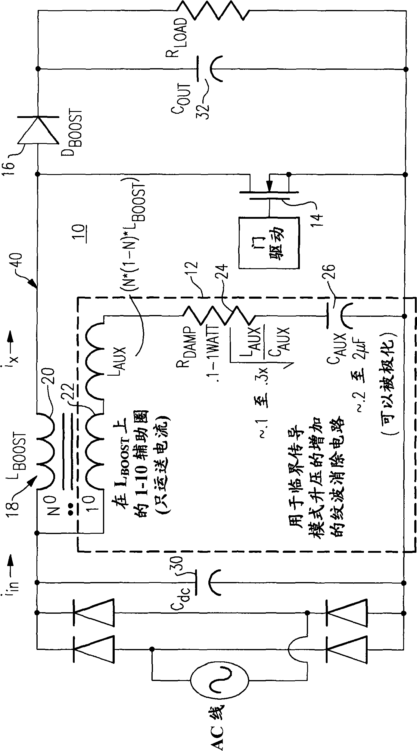
[0030] figure 1 A boost converter 10 including a boost inductor value reduction circuit 12 according to one embodiment of the invention is illustrated. The boost inductor value reduction circuit 12 is a lightweight, inexpensive and compact ripple cancellation circuit when compared to conventional filter structures. The boost inductor value reduction circuit 12 operates to generate a high frequency current signal that substantially cancels the high frequency ripple current that is conducted back to the AC line input side of the boost converter 10, said high frequency ripple The ripple current is generated by the switching components of the boost converter 10 . According to one embodiment, it can be seen that the switching components of the boost converter 10 include a MOSFET 14 and a boost diode 16 .
[0031] Although boost converter 10 is shown with an AC line input, the invention is not so limited; and it will be appreciated that the principles described herein apply equall...
PUM
 Abstract
Description
Claims
Application Information