
Cross-winding device for a textile machine which produces cross-wound bobbins

A traversing device and cross-winding technology, applied in the direction of transportation and packaging, thin material handling, conveying filamentous materials, etc., can solve the problems of unfavorable effects of yarn material accumulation, adverse effects of unwinding characteristics, etc., and achieve spring characteristics smooth curve effect

Active Publication Date: 2009-09-16
ZHUOLANG INTELLIGENT MACHINERY CO LTD
View PDF2 Cites 3 Cited by
  • Summary
  • Abstract
  • Description
  • Claims
  • Application Information

AI Technical Summary

Problems solved by technology

If no special measures are taken, this return arc leads to accumulations of yarn material in the edge region of the cross-winding drum, which, for example, has a serious adverse effect on the unwinding behavior of such cross-winding drums.
This accumulation of yarn material can also have serious adverse effects in other subsequent processes, such as when dyeing such bobbins

Method used


Image

  • Cross-winding device for a textile machine which produces cross-wound bobbins
  • Cross-winding device for a textile machine which produces cross-wound bobbins
  • Cross-winding device for a textile machine which produces cross-wound bobbins

Examples


Embodiment Construction

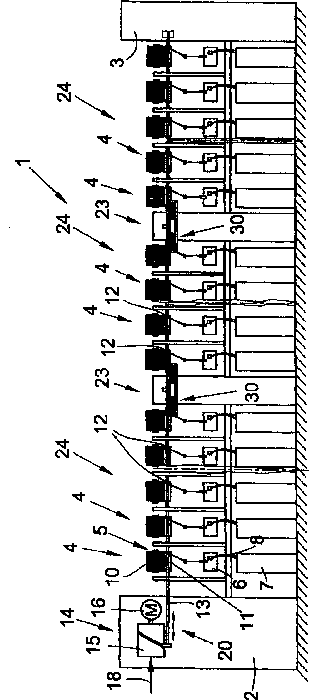
[0034] figure 1 The front view schematically shows a textile machine (in this example an open-end rotor spinning machine) for manufacturing cross-winding bobbins. Such a textile machine 1 generally has end frames 2 , 3 and a plurality of work stations 4 arranged between the end frames 2 , 3 . Here, the individual workstations 4 are arranged in sections, ie, for example, 24 workstations 4 form a machine section 24 , of which 12 are arranged at the machine front and 12 at the machine rear. The machine segments 24 are each mounted on a machine support 39 in the region of their segment boundaries 23 .

[0035] Each station 4 has an open-end spinning device 6 and a winding device 5, wherein the fiber sliver 8 provided in the spinning barrel 7 is converted into a yarn 9 in said spinning device 6, and then the yarn 9 A cross bobbin 10 is wound on the winding device 5 . Here, the crosswinding drum 10 is held rotatably in a creel, not shown, and is rotated by means of a drive roller...


PUM


Abstract

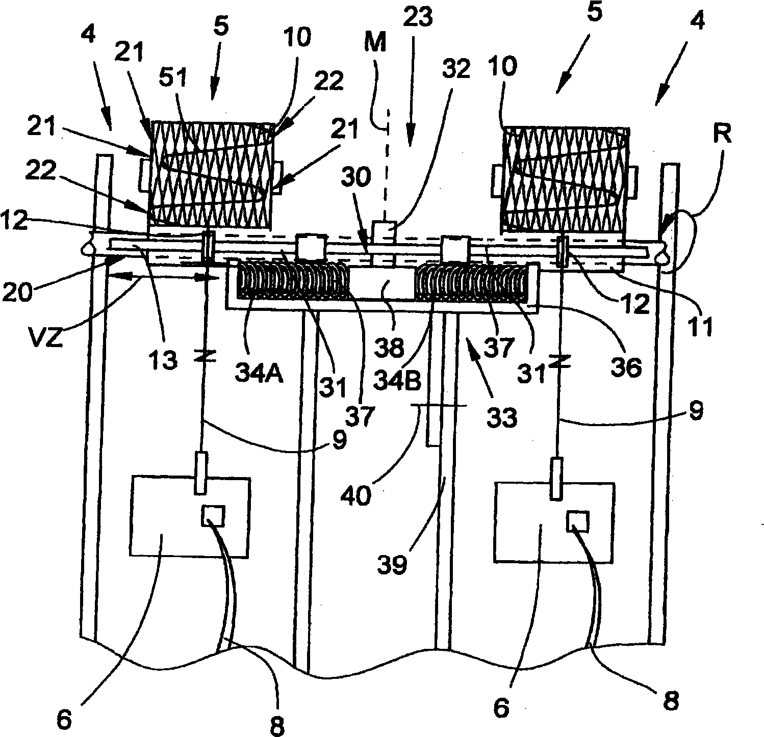
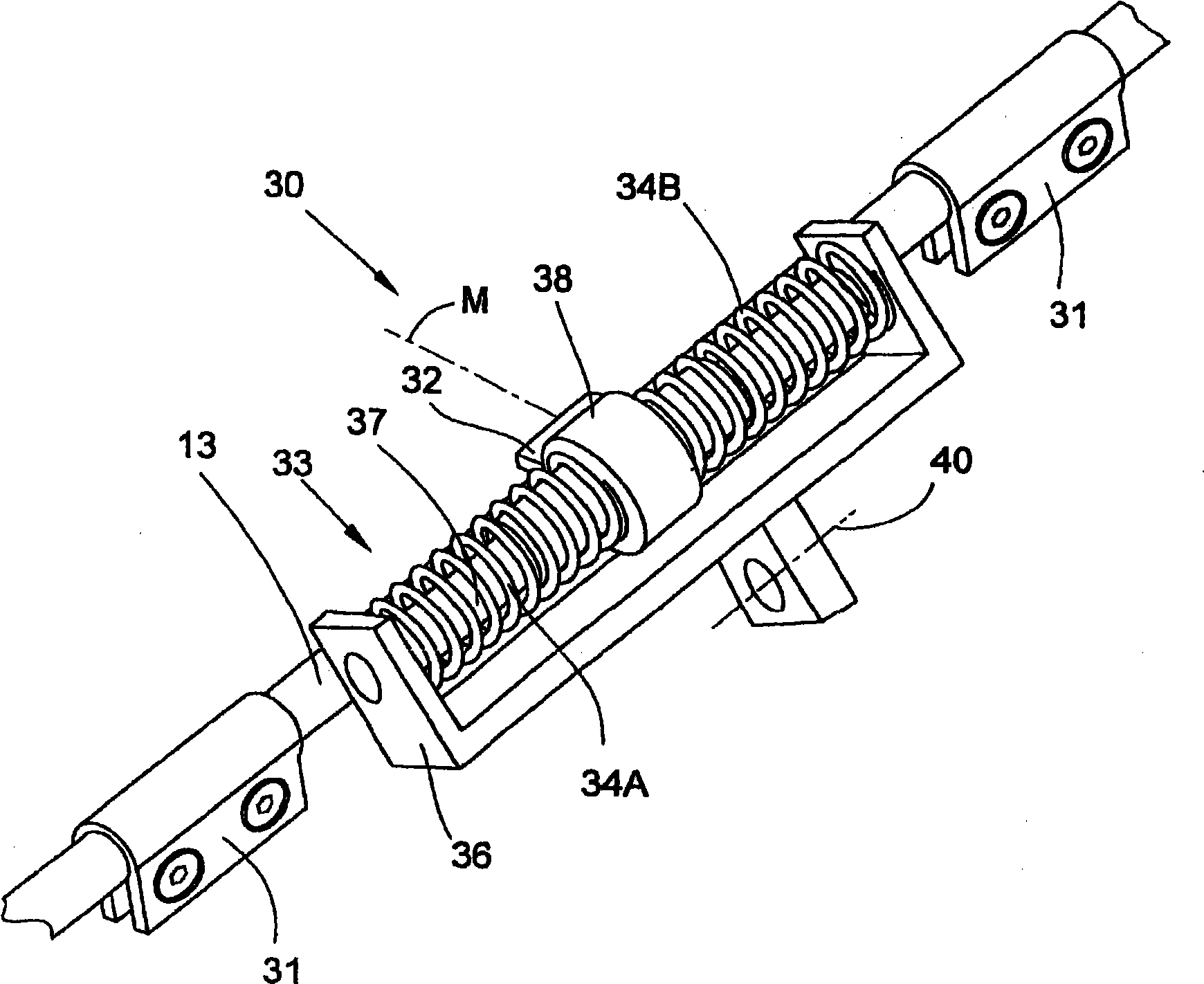
The invention relates to a cross-winding device (20) for a textile machine (1) which produces cross-wound bobbins and which has numerous operating positions (4), and which has a thread carrier rod (13) extending in a longitudinal direction relative to the machine and actuated in a traverse direction and on which cross-winding thread guides (12) are fixed. The cross-winding device (20) is also equipped with a so-called edge transferring device (18) which ensures that the cross-winding thread guides (12) run up to both inner (21) and outer (22) reversal points. In addition, the cross-winding device (20) has at least one energy storage unit (30) which supports the change of direction of the thread carrier rod (13) in the area of the reversal points (21, 22). According to the invention, it is provided that driver elements (31) are arranged on the thread carrier rod (13) which work together alternately in the cross-winding end areas thereof with a mechanical stop (32) of a spring system (33) which is formed as an energy storing unit (30). Said spring system (33) has at least two prestressed spring elements (34A, 34B) which lie on opposite sides of the mechanical stop (32) and which are formed and positioned such that the spring system (33), originating from a fulcrum (M) and going toward both sides, has for each side a decreasing spring characteristic (45, 46).

Description

technical field [0001] The invention relates to a yarn traversing device for a textile machine for producing cross-wound bobbins according to the preamble of claim 1 . Background technique [0002] Yarn traversing devices with traversing yarn guides (which are fixed on the yarn guide rods extending in the longitudinal direction of the machine) have already been disclosed (especially in connection with open-end rotor spinning machines), and in a large number of patent documents ( For example: US-PS 6,027,065) and in various specifications of textile machine manufacturers have been described in detail. Such a yarn traversing device, such as that described on page 1.2.5 of the specification of AUTOCORO from the Schlafhorst company, usually has a traversing drive device arranged at the end of the machine, for example, a grooved cylinder rotated by an electric motor drive. in the form of rolls. [0003] The yarn guide rod extending in the longitudinal direction of the machine i...

Claims


Application Information

Patent Timeline
Patent Type & Authority Applications(China)
IPC IPC(8): B65H54/28B65H54/32
CPCB65H54/2809B65H54/2818B65H2701/31B65H54/386B65H54/2881
Inventor 斯文·布特切考
Owner ZHUOLANG INTELLIGENT MACHINERY CO LTD
Learn More