Inverse control system of trolley locomotive

A technology for inverter control and power supply locomotives, applied in power lines, vehicle parts, transportation and packaging, etc., can solve the problems of current impact, poor track return, low power supply terminal voltage, etc., to avoid current impact and avoid contact jitter , adapt to a wide range of effects

CN101537800AInactive Publication Date: 2009-09-23天津方圆电气有限公司
0 Cites 1 Cited by

Patent Information

Authority / Receiving Office
CN · China
Patent Type
Applications(China)
Current Assignee / Owner
Publication Date
2009-09-23
Estimated Expiration
Not applicable · inactive patent

Smart Images

  • Figure 1
    Figure 1
  • Figure 2
    Figure 2
  • Figure 3
    Figure 3
Patent Text Reader

Abstract

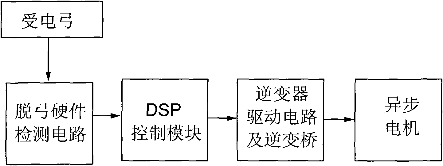
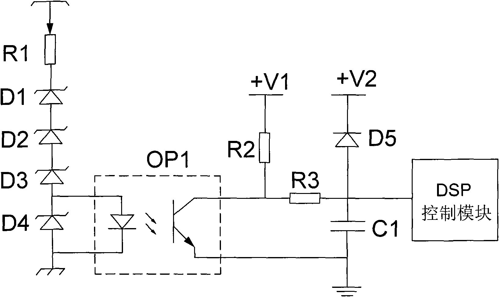
The invention relates to an inverse control system of a trolley locomotive, comprising a pantograph type current collector, a bow-off hardware detection circuit, a DSP control module, an inverter drive circuit, an inverse bridge and an asynchronous motor; wherein, one end of the pantograph type current collector is connected with a trolley network, and the other end thereof is connected with an input end of the bow-off hardware detection circuit; an output end of the bow-off hardware detection circuit is connected with an input end of the DSP control module, and an output end of the DSP control module is connected with the inverter drive circuit and the inverse bridge which are also connected with the asynchronous motor. The invention combines the bow-off hardware detection circuit and the DSP control module, so as to realize smooth transition of an electroless spanning mode of a traction system, thus improving the traction efficiency, avoiding the current impact caused by restoring the network, having the characteristics of short spanning time, reliable performance and wide application scope, and being suitable for the working condition of domestic trolley power supply traction locomotives.
Need to check novelty before this filing date? Find Prior Art

Description

technical field

[0001] The invention belongs to the field of overhead line power supply locomotives, in particular to an inverter control system for overhead line type power supply locomotives. Background technique

[0002] In the field of wire-powered locomotives, due to the limitations of the power supply conditions of the power grid and the partition power supply mode of long-distance lines, the pantograph (front-end collector) will inevitably face short-term disconnection or short-term power loss through non-electric partitions , often causes the DC voltage of the busbar to be exhausted and causes the DC undervoltage of the inverter, so that the traction system enters the undervoltage protection state; The dynamic current, and the necessary variables must be initialized to restart the traction system, resulting in a significant reduction in traction efficiency. In order to overcome the above problems, the inverter can usually be used to dynamically detect the DC bus vol...

Examples

Embodiment Construction

[0020] Embodiments of the present invention will be described in further detail below in conjunction with the accompanying drawings.

[0021] An inverter control system for a trolley-type power supply locomotive, such as figure 1 As shown, it consists of a pantograph, a bow-off hardware detection circuit, a DSP control module, an inverter drive circuit, an inverter bridge, and an asynchronous motor connected in sequence. The voltage, off-bow hardware detection circuit is used to detect the grid voltage of the power grid and output the detection signal to the DSP control module. After processing the preset control program inside the DSP control module, the control signal is output to the inverter drive circuit and the inverter bridge to control the asynchronous motor work. In this embodiment, the DSP control module adopts TMS320LF2407A chip.

[0022] The specific structure of the off-bow hardware detection circuit is as follows: figure 2 As shown, the input side of the bow-...