Construction method for building concrete superface with surface modeling

A technology of curved surface modeling and concrete roof, which is applied in the direction of building structure, building, building components, etc. It can solve the requirements of non-standard steel formwork hoisting, installation, commissioning, and disassembly, which consume a lot of time and manpower, and cannot ensure the curvature accuracy of thin plate structures. , high cost of construction tooling preparation, etc., to achieve the effect of ensuring the quality of the entity and the appearance curve, saving labor and material input, and saving energy consumption for hoisting

Active Publication Date: 2011-04-06
THE SECOND CONSTR ENG CO LTD OF CHINA CONSTR THIRD ENG BUREAU +3
View PDF0 Cites 0 Cited by
  • Summary
  • Abstract
  • Description
  • Claims
  • Application Information

AI Technical Summary

Problems solved by technology

[0005] Since the customized non-standard steel form is specially made for the construction of a certain building, it is difficult to be used again for the construction of the top surface of other special-shaped buildings; due to the heavy weight of the customized non-standard steel form, it also consumes more energy for hoisting; The hoisting, installation, commissioning, and disassembly of customized non-standard steel molds consume a lot of time and manpower
These factors lead to very high preparation costs for construction tooling, and also increase construction costs
[0006] Especially for thin-slab structures with curved concrete surfaces, since the curvature of each point is different, the amount of elevation data provided on the drawings is limited. If the existing method is used for construction, it cannot meet the construction needs and cannot ensure the accuracy requirements of the curvature of the thin-slab structure

Method used


Image

  • Construction method for building concrete superface with surface modeling
  • Construction method for building concrete superface with surface modeling
  • Construction method for building concrete superface with surface modeling

Examples


Embodiment Construction

[0020] According to the present invention, firstly, the top surface of the building or the structure with the curved shape is thinned, so as to obtain more elevation data according to the limited elevation data marked on the drawings.

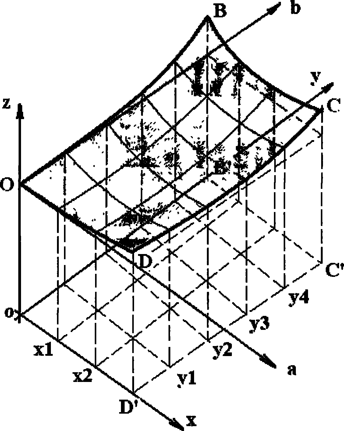
[0021] Specifically, as figure 1 As shown, if the elevation data of the four corner points of a part of the space hyperboloid OBCD are marked on the drawing, the corner point O with a lower elevation of the curved plate can be designed as the coordinate origin to establish an ab-direction coordinate system; Perform horizontal orthographic projection on the reference plane to obtain the quadrilateral oB'C'D'; then divide the quadrilateral oB'C'D' into several grids, for example, insert two points with coordinates x1 and x2 on the side of oD', Insert four points y1, y2, y3, and y4 on oB', so that the quadrilateral oB'C'D' is divided into 3×5=15 small quadrilaterals, and 4×6=24 nodes appear, so we can find The corresponding 24 nodes on the space ...


PUM


Abstract

The invention relates to a construction method for building concrete superface with surface modeling, which comprises the following steps: a horizontal projection is carried out on a space curved surface structure; a horizontal projection plane is divided into a plurality of grids; by establishing a local coordinate system, the elevation on the space curved surface corresponding to each grid nodein the coordinate frame of the horizontal projection plane is figured out; according to each elevation data, the position of the cross rod of each load steel tube is determined so as to finish bridging; and then according to the elevation data, a back purlin is formed, and finally the formed back purlin is fixed on the corresponding cross rod of each load steel tube; a defined of water reducing agent and fly ash with small grain diameter are doped into concrete; firstly, pump pipes are arranged in the lowest position of a double-parabolic slab, distribute materials from bottom to top along a diagonal direction, pushes toward the highest point; a pump truck alternatively cuts materials at both sides of the diagonal, builds and vibrates, which is shot by people in real time. The construction method can reduce the difficult problem and strength of the construction, has fast construction process, low construction cost and high construction quality.

Description

technical field [0001] The invention relates to a method for constructing a concrete top surface of a building or a structure with a curved shape, in particular to a construction method for a concrete roof with a curved shape. [0002] In this patent specification, the term "curved surface" on the top surface of a building includes, but is not limited to: hyperboloid, double slope, single curved single slope, sphere, ellipsoid, ellipse, parabola, the mutual combination of these elements and further combinations of planes, and so on. [0003] In particular, in this patent specification, the term "hyperboloid" about the top surface of a building includes not only a curved surface whose cross-section is a hyperbola in the mathematical sense, but also includes that the projections on the xz and yz planes in the xyz three-dimensional coordinate system are both curves any surface. Background technique [0004] With the development of the construction industry, there are more and...

Claims


Application Information

Patent Timeline
Patent Type & Authority Patents(China)
IPC IPC(8): E04B7/10
Inventor 张琨黄刚汤丽娜林伟洪周俊吕雄邓兰艳陈松
Owner THE SECOND CONSTR ENG CO LTD OF CHINA CONSTR THIRD ENG BUREAU
Why Eureka
Try Eureka