Method for obtaining optical path difference of optical switch and device

An optical switch, optical path difference technology, applied in the direction of testing optical performance, etc., can solve the problem that the optical switch optical path difference index cannot be provided.

Inactive Publication Date: 2009-09-23
BEIHANG UNIV
View PDF0 Cites 7 Cited by
  • Summary
  • Abstract
  • Description
  • Claims
  • Application Information

AI Technical Summary

Problems solved by technology

Especially in precise delay or phase control systems, the required accuracy is on the order of picoseconds or sub-picoseconds, and the optical path difference of optical switches is generally on the order of picoseconds. In this case, the optical path differ

Method used


Image

  • Method for obtaining optical path difference of optical switch and device
  • Method for obtaining optical path difference of optical switch and device
  • Method for obtaining optical path difference of optical switch and device

Examples


Embodiment Construction

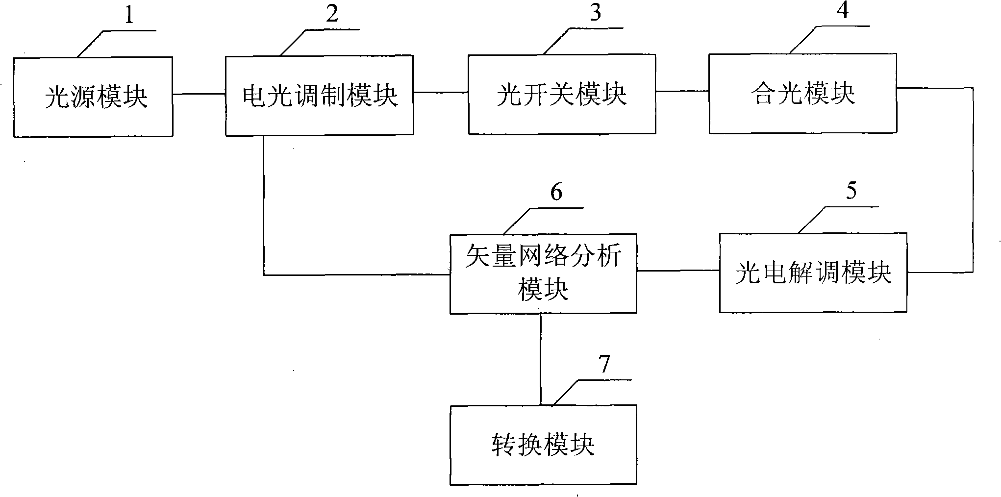
[0020] In a solution for obtaining the optical path difference of an optical switch provided by an embodiment of the present invention, first, the input electrical signal provided by the vector network analysis module is electro-optical modulated onto an optical carrier to obtain an optical signal, and then the optical signal is passed through the optical switch After switching to one channel, one optical fiber transmission signal is obtained through optical combination. After the optical fiber transmission signal is photoelectrically demodulated, the vector network analysis module obtains the group delay of the two internal channels of the optical switch, and the optical switch obtained according to the vector network analysis The group delay of the two internal paths, and finally the group delay of the two paths is converted to obtain the optical path difference between the two paths inside the optical switch; if the optical fiber transmission signal obtained after optical com...


PUM


Abstract

The invention relates to a method for obtaining optical path difference of an optical switch and a device. The proposal thereof is as follows: firstly an input electric signal provided by a vector network analysis module is modulated on an optical carrier by electric light to obtain an optical signal; then the optical signal is switched to an access by the optical switch, and a path of optical fiber transmission signal is obtained by combined light; the optical fiber transmission signal are demodulated by photoelectricity and then the group delay of the two accesses in the optical switch is obtained by vector network analysis; and finally the group delay of the two accesses is switched to obtain the optical path difference of the two accesses in the optical switch. The invention realizes the measurement of little optical path difference in the optical switch, thus improving the delay precision of an implementation system of the optical switch of the OTTD technology.

Description

technical field [0001] The invention relates to a photoelectric detection technology, in particular to a method and a device for obtaining the optical path difference of an optical switch. Background technique [0002] At present, OTTD (Optical True Time Delay, optical real-time delay line) technology mainly uses optical switches to control arrays of different fiber lengths to realize optical real-time delay. Other delay indicators such as time, isolation, and insertion loss are mainly determined by optical switches, so the performance of optical switches is also a major factor in the performance of OTTD technology. Especially in precise delay or phase control systems, the required accuracy is on the order of picoseconds or sub-picoseconds, and the optical path difference of optical switches is generally on the order of picoseconds. In this case, the optical path difference of optical switches cannot Neglected, but at present, optical switch manufacturers only provide conve...

Claims


Application Information

Patent Timeline
IPC IPC(8): G01M11/02
Inventor 张春熹张晓青胡姝玲欧攀胡汉伟陈亦男
Owner BEIHANG UNIV
Why Eureka
Try Eureka