Detecting method of vehicle GPS velocimeter

A technology of motor vehicles and speedometers, which is applied in the direction of testing/calibration of instruments, speed/acceleration/shock measuring equipment, and measuring devices, etc. It can solve the problems of inaccurate speed measurement error detection, inability to detect, limit, etc., to improve accuracy Reliability, easy promotion and application, and the effect of reducing cumbersome dangers

Inactive Publication Date: 2009-09-23
NAT INST OF METROLOGY CHINA
View PDF0 Cites 19 Cited by
  • Summary
  • Abstract
  • Description
  • Claims
  • Application Information

AI Technical Summary

Problems solved by technology

Under normal circumstances, the speed index detection result of the high-precision motor vehicle GPS speedometer that can work normally is very accurate according to this method, and the deviation from the theoretical speed value generally does not exceed ± 0.01km / h, but the following deficiencies exist in the prior art Advantages: (1) each test of the on-site road comparison test method in the prior art needs to put forward higher requirements to the test site, test vehicles and environmental conditions, staffing, although it can be carried out according to the requirements of the high-precision motor vehicle GPS It is detected in the actual working state, but it cannot realize the detection of the repeatability of the measurement at the same speed point
Moreover, the non-contact speedometer as a comparison tool will be affected by various on-site actual factors during the road test process, and its speed measurement indicators and traceability methods have not been recognized by the international measurement field of motor vehicle speed; (2) In the existing technology, the GPS signal simulator is used to detect the high-precision motor vehicle GPS speedometer, and the detection method of laboratory simulation is adopted, which often ignores the adverse effects of factors such as satellites, atmosphere, and on-site environment on the GPS satellite signal. The actual use and measurement status of the high-precision motor vehicle GPS speedometer is quite different, and the test results cannot truly reflect the technical index level of the high-precision motor vehicle GPS speedometer in the actual use state, so it is impossible to accurately detect the speed measurement error
Therefore, this prior art is subjected to bigger restriction when popularizing and applying
[0005] In short, in the prior art, the on-site road comparison test method is time-consuming and laborious, and the measurement repeatability cannot be tested, and the laboratory simulation speed test method cannot be accurate and reliable according to the actual working status of the high-precision motor vehicle GPS speedometer. It is difficult to popularize in the measurement and detection industry of high-precision motor vehicle GPS speedometer

Method used


Image

  • Detecting method of vehicle GPS velocimeter
  • Detecting method of vehicle GPS velocimeter
  • Detecting method of vehicle GPS velocimeter

Examples


Embodiment 1

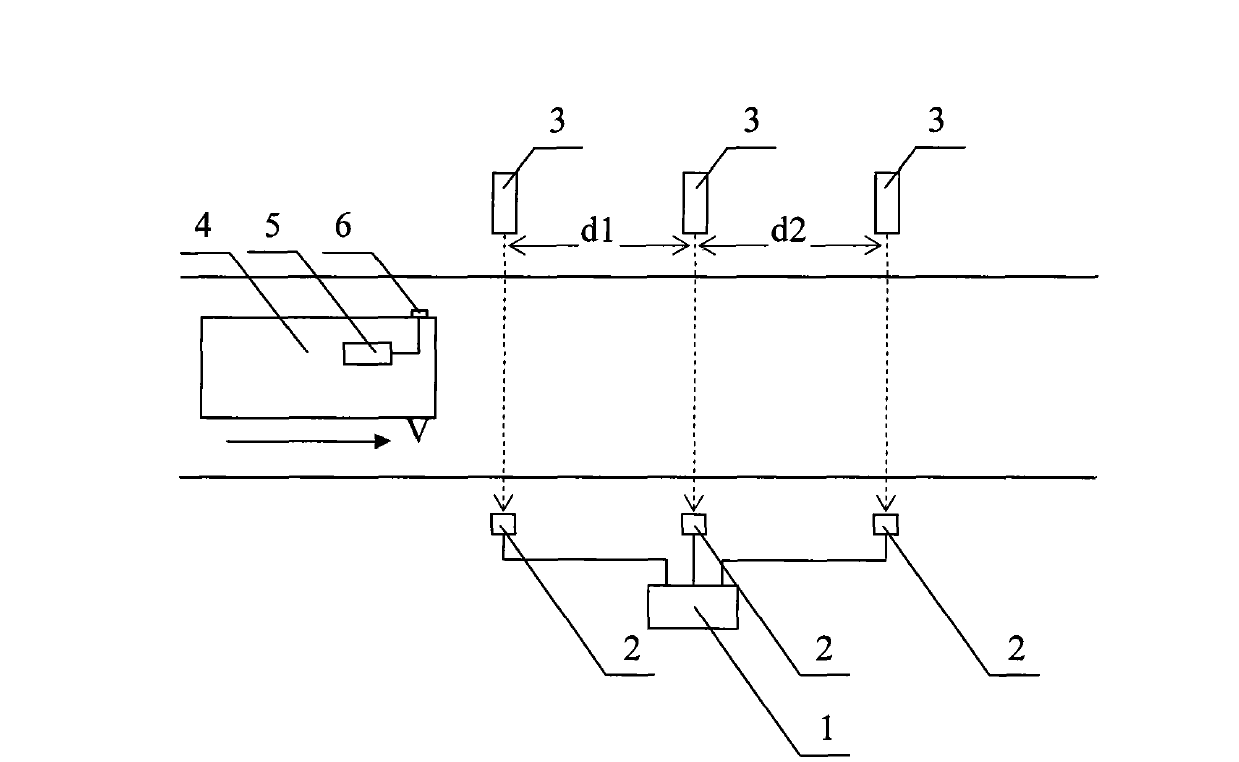
[0052] This embodiment detects the speed measurement error of the high-precision motor vehicle GPS speedometer. Three laser receivers and three laser emitters are placed on both sides of the test lane at intervals of 5m to ensure that the three laser beams are parallel to each other and perpendicular to the driving direction of the test vehicle. The test motor vehicle runs in a straight line at a constant speed of about 113km / h and passes through the speed measurement area, and the GPS signal recording / playback device simultaneously records the satellite GPS signal. The average speed values ​​V1 (113.92km / h) and V2 (113.92km / h) of the test motor vehicle measured by the single-chip microcomputer, the deviation is 0.00km / h, which is less than the accuracy index of the high-precision motor vehicle GPS speedometer manufacturer 0.1km / h h, the test is valid. Taking the average speed V3 (113.92km / h) between the first beam and the third beam of the test vehicle as the reference speed...

Embodiment 2

[0055] This embodiment detects the repeatability of the speed measurement of the high-precision motor vehicle GPS speedometer. Three laser receivers and three laser emitters are placed on both sides of the test lane at intervals of 5m to ensure that the three laser beams are parallel to each other and perpendicular to the driving direction of the test vehicle. The test motor vehicle drives in a straight line at a constant speed of about 61km / h and passes through the speed measurement area, and the GPS signal recording / playback device simultaneously records the satellite GPS signal. The average speed values ​​V1 (61.22km / h) and V2 (61.22km / h) of the test motor vehicle measured by the single-chip microcomputer, the deviation is 0.00km / h, which is less than the accuracy index of the high-precision motor vehicle GPS speedometer manufacturer 0.1km / h h, the test is valid. Taking the average speed V3 (61.22km / h) between the first beam and the third beam of the test vehicle as the re...


PUM


Abstract

The invention provides a detecting method of a vehicle GPS velocimeter, belonging to the field of measuring and surveying. The invention uses three light beam light shielding velocity measuring standard devices to directly and actually detect the velocity of a satellite GPS signal and calibrates a standard on the detecting spot; the velocity is memorized by a recording apparatus/ a playback apparatus; the playback of the GPS signal in a laboratory is used for ensuring the high-precision vehicle GPS velocimeter to accurately detect the velocity in the laboratory with a special velocity value and trace to the source to the SI base unit of length and time. The invention depends on the GPS signal which is calibrated on the spot to be a quantity transmission object, combines the truth and the reliability of a road test with the convenience and the agility of laboratory simulation, completes the detection such as velocity error detection, repeat detection, and the like, with the high-precision vehicle GPS velocimeter in the laboratory, improves the accuracy and the reliability of detecting results, reduces complex and dangerous vehicle high-speed tests on the spot, is convenient and feasible, improves work efficiency and is easy popularization and application.

Description

technical field [0001] The invention belongs to the field of measurement and measurement, and in particular relates to a detection method for a high-precision motor vehicle GPS speedometer. Background technique [0002] In May 2000, after the United States canceled the SA restrictions, the accuracy of GPS single-point positioning and speed measurement has been significantly improved, and GPS technology has been widely used in the field of motor vehicle performance testing and dynamic navigation. The motor vehicle speedometer based on GPS speed measurement technology usually uses the method of position difference to determine the driving speed of the motor vehicle. Using this method to measure the transient driving speed, the real-time performance and accuracy cannot meet the measurement requirements of motor vehicle speed detection. Therefore, GPS speedometers and navigators that use position differential speed measurement are limited to civilian use. With the further devel...

Claims


Application Information

Patent Timeline
Patent Type & Authority Applications(China)
IPC IPC(8): G01P21/02G01V8/20
Inventor 孙桥蔡常青张跃胡红波王肖磊
Owner NAT INST OF METROLOGY CHINA
Why Eureka
Try Eureka