
System for splicing display screens and control method thereof

A technology for splicing and controlling interfaces, applied in the splicing system and its control field, can solve the problems such as the control module cannot control the video processing module, the glass panel and the display screen are easily damaged, and the I2C bus cannot work normally, and the image effect can be enhanced. , The effect of convenient maintenance and replacement, and fast start-up speed

Inactive Publication Date: 2009-09-23
上海长臣电子设备有限公司
View PDF2 Cites 17 Cited by
  • Summary
  • Abstract
  • Description
  • Claims
  • Application Information

AI Technical Summary

Problems solved by technology

In the initial design, the control module controls the video processing module through I2C, but in the debugging process, it is found that because there are multiple devices mounted on the I2C bus, when there is a problem with some other device on the I2C bus, the entire I2C The bus is not working normally, so the control module cannot control the video processing module at this time, and the system cannot work normally.
[0006] In addition, there are still these defects in the mechanical structure of the existing multi-screen system: first, the display screen of each display unit is fastened to the horizontal frame and the vertical frame by screws at the same time, and the screw holes are easy to cause damage to the screen. In use, if a display fails, the entire rack needs to be disassembled before a display can be disassembled, resulting in very troublesome maintenance and replacement of the display; secondly, considering the surface flatness and aesthetics of the splicing display device, Usually, a large glass panel is installed in front of the display screen, but fastening with screws is easy to damage the glass panel and the display screen, and the gap between the display screen and the display screen can also be seen through the glass panel, which still affects the aesthetics

Method used


Image

  • System for splicing display screens and control method thereof
  • System for splicing display screens and control method thereof
  • System for splicing display screens and control method thereof

Examples


Embodiment Construction

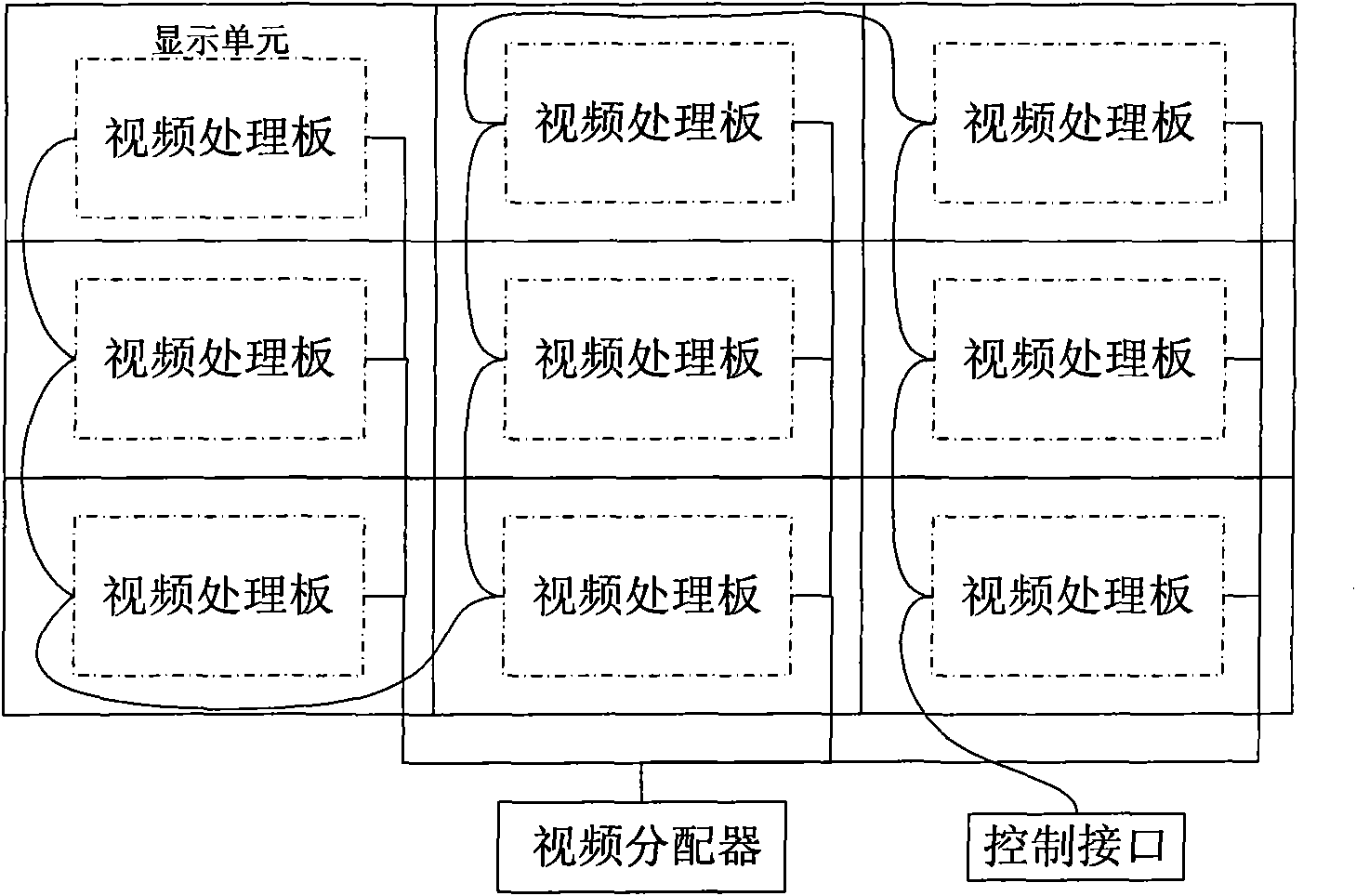
[0048] Such as figure 1 As shown, a splicing system includes a plurality of spliced ​​display units, a video distributor and a control interface, and each display unit includes a display screen and a video processing board, wherein the display screen and the video processing board are connected through a display interface connected.

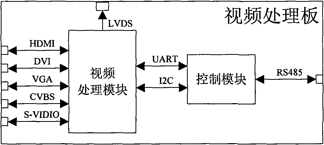
[0049] Such as figure 2 As shown, the video processing board includes a video processing module (ASIC chip can be used) and a control module (ARM chip can be used), and the video processing module and the control module are connected through a UART interface and an I2C interface. said through the UART interface and the I 2 The dual-interface method of C interface ensures the stability and smoothness of the multi-screen system.

[0050] Wherein, the control module of each of the video processing boards is connected to the control interface through an RS485 interface.

[0051]The video processing board performs video control through the contro...


PUM


Abstract

The invention provides a system for splicing display screens and a control method thereof. The system comprises a plurality of spliced display units, a video distributor and a control interface, wherein, each display unit comprises a display screen and a video processor board; the display screen is connected with the video processor board via a display interface; the video processor board is connected with the control interface; and a video processing module is connected with a control module via a UART (universal asynchronous receiver / transmitter) interface and an I2C (inter-integrated circuit) interface. The control method comprises the following steps: accomplishing the original task of an I2C bus through a UART bus to prevent the system from stopping responding to user commands when the I2C bus of the system does not work properly; and automatically switching to the control mode of the I2C bus to prevent the video processing module from being affected when the I2C bus resumes. The invention has the advantages of high startup speed, high stability, simple development and non-interacting processing units; the tasks are smooth and stable; and in addition, the invention has the advantages of convenient maintenance and replacement.

Description

technical field [0001] The invention belongs to the technical field of splicing screen display, and in particular relates to a splicing screen system and a control method thereof. Background technique [0002] Chinese Patent No. 200810026939.X is a multi-screen splicing method and device. The multi-screen splicing device includes an imaging module, a control module and an image segmentation and splicing module. The bandwidth standard adjusts the output refresh rate of the GPU so that the output resolution of the GPU meets the requirements of the total stitching resolution. The image segmentation and stitching module splits the video data and realizes the standard stitching output under the synchronization of the standard pixel clock of the control module. It can increase the output resolution of the GPU to achieve high-resolution multi-screen splicing. But this device is a computer-based system, which has the disadvantages of high cost, slow startup speed and low stability....

Claims


Application Information

Patent Timeline
IPC IPC(8): G09G5/14G09G5/00
Inventor 吴锡宏章晟孙健
Owner 上海长臣电子设备有限公司
Learn More