Eureka AIR delivers breakthrough ideas for toughest innovation challenges, trusted by R&D personnel around the world.

Transreceiver and zero intermediate frequency emission calibrating method

A transceiver, zero-IF technology, applied in transmission systems, electrical components, etc., can solve the problems of inability to guarantee the application of the factory calibration table, high cost of communication transceivers, low cost and volume, etc., to overcome carrier leakage and sidebands. Suppression, cost reduction, effect of small architecture

Inactive Publication Date: 2009-09-23
深圳市恒程汇文化科技有限公司
View PDF0 Cites 21 Cited by
  • Summary
  • Abstract
  • Description
  • Claims
  • Application Information

AI Technical Summary

Problems solved by technology

The cost and volume of this existing base station are very low, but there is an Achilles heel, that is, this calibration method is carried out at the factory, and the calibration table is fixed after it is generated. With the increase of the working time of the base station, the factory calibration cannot be guaranteed. The table is still applicable. Moreover, it is carried out in a normal temperature working environment when leaving the factory, which is different from the normal working environment of the base station. When the external environment changes, especially when the temperature changes, it must be calibrated again to ensure the communication performance of the base station , but the existing base stations cannot be calibrated and adjusted at any time after leaving the factory, and cannot adapt to changes in the external environment such as temperature
[0005] In order to solve the above problems, some base stations use additional receiving channels to achieve self-adaptive calibration. access, resulting in too high a communication transceiver cost

Method used

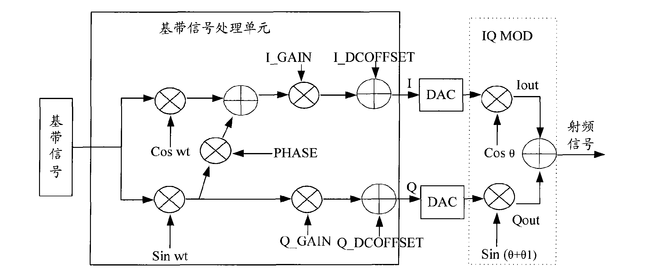

Image

  • Transreceiver and zero intermediate frequency emission calibrating method
  • Transreceiver and zero intermediate frequency emission calibrating method
  • Transreceiver and zero intermediate frequency emission calibrating method

Examples


Embodiment Construction

[0039] The present invention will be described in further detail below through specific embodiments and accompanying drawings.

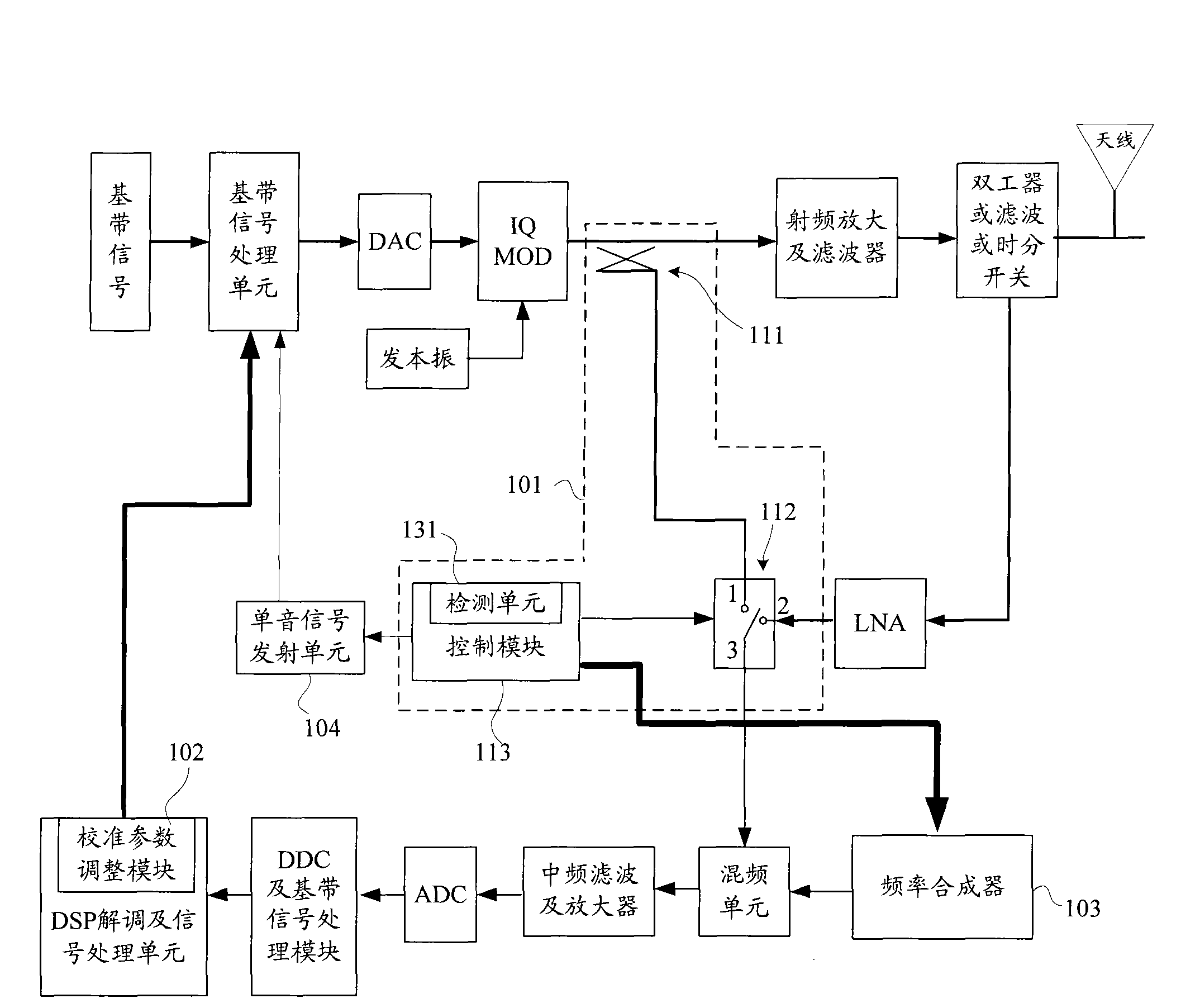
[0040] figure 1 It is a structural schematic diagram of an embodiment of the transceiver according to the present invention. see figure 1 , the transceiver includes a transmit path and a receive path. In the transmission path, the baseband signal is processed by the baseband signal processing unit, digital-to-analog signal converter (DAC), and zero-IF signal modulator (IQ MOD) to obtain a radio frequency signal after adding a local oscillator, and the radio frequency signal is amplified by radio frequency And filter, and duplexer or filter or time-division switch processing, and finally transmitted by the antenna. On the receiving path, the signal received by the antenna is processed by a duplexer or filter or a time-division switch, and then sent to a low-noise amplifier (LNA). The receiver performs processing such as receiving the local oscilla...


PUM


Abstract

The invention discloses a transreceiver and a zero intermediate frequency emission calibrating method. The transreceiver comprises a zero intermediate frequency emission circuit and a receiving circuit, and also comprises a coupling module and a calibration parameter adjusting module, wherein the coupling module is arranged between the zero intermediate frequency emission circuit and the receiving circuit, and is used for coupling radio-frequency signals of the emission circuit to the receiving circuit; and the calibration parameter adjusting module is arranged on the receiving circuit, used for adjusting unbalance factors of the coupled signals in a close loop to make the signal quality index meet the predetermined demand, and uses the adjusted unbalance factors as calibration parametersto calibrate the emission signals of the emission circuit. The method of the invention can adaptively adjust the calibration parameters of the zero intermediate frequency signals with lower cost according to environmental requirements.

Description

technical field [0001] The invention relates to the transceiver technology of a communication system, in particular to a transceiver with a zero-IF transmission path and a zero-IF transmission calibration method. Background technique [0002] In the field of communication in recent years, due to the development of devices, more and more zero-IF technology has been widely used and gradually matured. With the development of zero-IF technology, the traditional superheterodyne secondary frequency conversion scheme is increasingly being replaced. The biggest advantage of the transceiver using zero-IF technology is that the IF filter circuit, IF mixer and IF local oscillator are omitted, which simplifies the channel, reduces the cost of the channel, and reduces the size of the single board. These advantages cater to the miniaturization and low cost requirements of today's transceivers, especially communication base stations. Therefore, the transceiver of the zero-IF technology h...

Claims


Application Information

Patent Timeline
Patent Type & Authority Applications(China)
IPC IPC(8): H04B1/76H04B1/40
Inventor 王剑
Owner 深圳市恒程汇文化科技有限公司
Why Eureka
Eureka Blog
Learn More