Suspension bed hydrocracking catalyst and preparation method and application thereof

A hydrocracking and catalyst technology, applied in physical/chemical process catalysts, metal/metal oxide/metal hydroxide catalysts, chemical instruments and methods, etc., can solve the problems of small application scale, poor economic rationality, complicated steps, etc. problems, achieve good performance, solve difficult processing, and uniform particle size

Active Publication Date: 2011-03-30
RES INST OF PETROLEUM PROCESSING SINOPEC
View PDF4 Cites 0 Cited by
  • Summary
  • Abstract
  • Description
  • Claims
  • Application Information

AI Technical Summary

Problems solved by technology

The above-mentioned reutilization method of catalytic cracking waste catalyst has complicated steps, small application scale and poor economic rationality
[0005] At present, there is no report on the preparation of heavy and residual oil hydrocracking catalysts using catalytic cracking spent catalysts as carriers

Method used


Image

  • Suspension bed hydrocracking catalyst and preparation method and application thereof
  • Suspension bed hydrocracking catalyst and preparation method and application thereof
  • Suspension bed hydrocracking catalyst and preparation method and application thereof

Examples


Embodiment 1

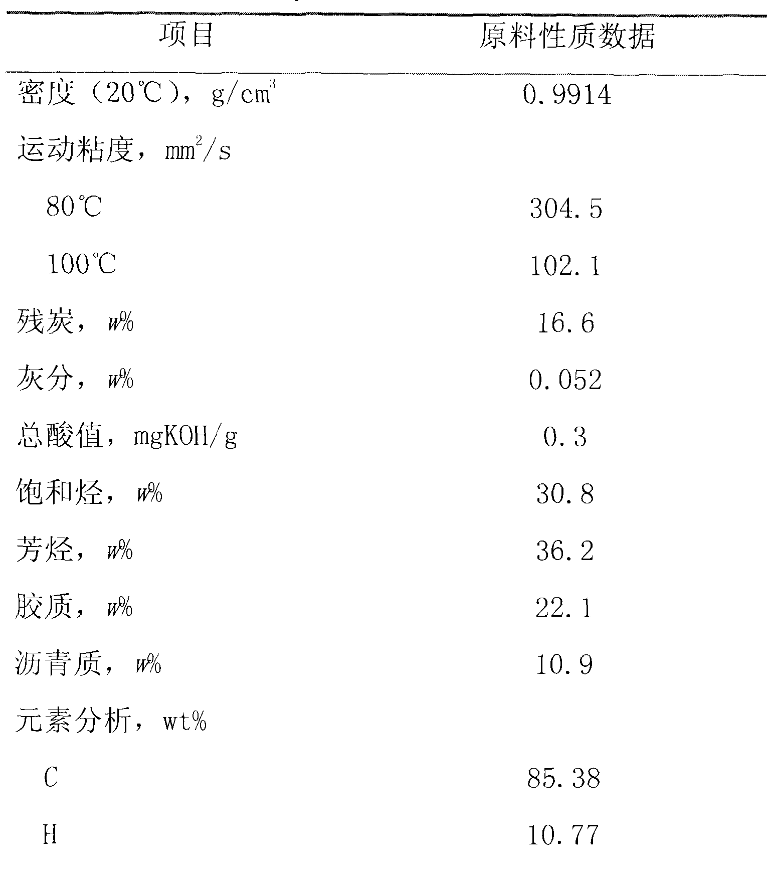
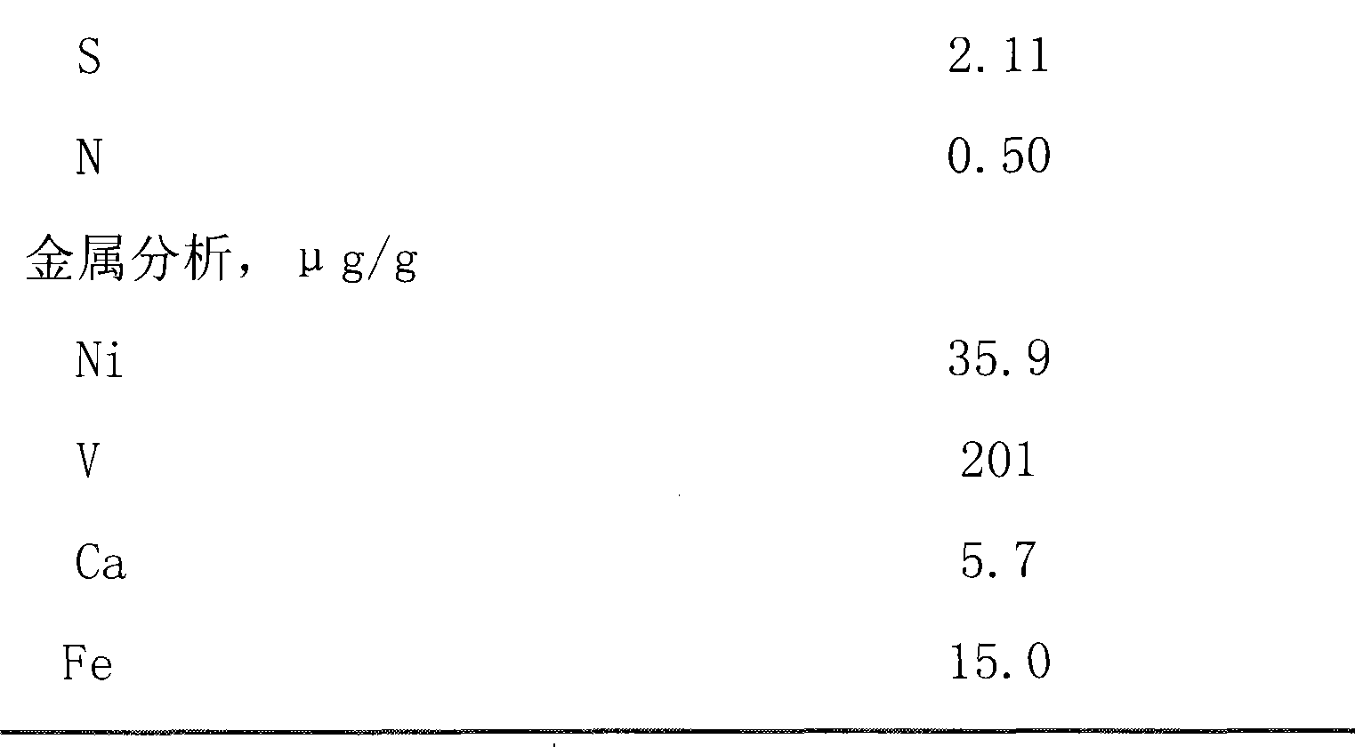
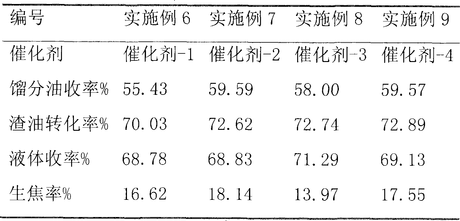
[0054] Spent catalyst from catalytic cracking (Shijiazhuang Refinery, Fe 2 o 3The content is 0.3wt%, and the specific surface area is 240m 2 / g) to sieve the part below 120 mesh, weigh 95.00g into a 250ml petri dish; weigh nickel nitrate Ni(NO 3 ) 2 .6H 2 O 19.47g into a beaker, then add 47.50g deionized water to dissolve; constantly stir the spent catalyst powder in the petri dish, add nickel nitrate aqueous solution drop by drop; dry at 100-120°C for 3h, and roast at 450°C for 3h to obtain Catalyst, designated Catalyst-1.

Embodiment 2

[0056] Spent catalyst from catalytic cracking (Shengli Petrochemical General Plant, Ni content 1900ug / g, V content 4100ug / g, specific surface area 150m 2 / g) to sieve the part below 120 mesh, weigh 95.00g to a 250ml petri dish; weigh 4.87g ammonium molybdate ((NH 4 ) 6 MO 7 o 24 .4H 2 (0) into a beaker, then add 47.50g deionized water to dissolve; constantly stir the waste catalyst powder in the petri dish, add ammonium molybdate aqueous solution drop by drop; dry 3h at 100~120°C; then weigh nickel nitrate (Ni( NO 3 ) 2 .6H 2 (0) 4.01g into a beaker, then add 48.50g deionized water to dissolve; constantly stir the waste catalyst powder in the petri dish, add nickel nitrate aqueous solution drop by drop; dry at 100~120°C for 3h, and roast at 450°C for 3h, A bimetallic catalyst with a molar ratio of molybdenum and nickel of 1:0.5 was obtained, which was designated as Catalyst-2.

Embodiment 3

[0058] Spent catalyst from catalytic cracking (Shijiazhuang Refinery, Fe 2 o 3 The content is 0.3wt%, and the specific surface area is 240m 2 / g) to sieve the part below 120 mesh, weigh 95.00g to 250ml petri dish; weigh 3.45g ammonium molybdate ((NH 4 ) 6 MO 7 o 24 .4H 2 (0) into a beaker, then add 47.50g deionized water to dissolve; constantly stir the waste catalyst powder in the petri dish, add ammonium molybdate aqueous solution drop by drop; dry 3h at 100~120°C; then weigh nickel nitrate (Ni( NO 3 ) 2 .6H 2 (2) 8.52g in the beaker, then add 48.50g deionized water to dissolve; constantly stir the waste catalyst powder in the petri dish, add nickel nitrate aqueous solution drop by drop; dry at 100~120°C for 3h, and roast at 450°C for 3h, A bimetallic catalyst with a molar ratio of molybdenum and nickel of 1:1.5 was obtained, designated Catalyst-3.


PUM

PropertyMeasurementUnit
particle diameteraaaaaaaaaa
specific surface areaaaaaaaaaaa
particle diameteraaaaaaaaaa

Abstract

The invention relates to a suspension bed hydrocracking catalyst which comprises a carrier and transitional metal loaded on the carrier, and the loading capacity of the transitional metal is 0.5-10 weight percent on the metal oxide basis; the transitional metal is selected from one or a plurality of types of VIB and VIII group metals, and the carrier is catalytic cracking dead catalyst with the grain size no less than 150Mum. The suspension bed hydrocracking catalyst can be used for the suspension bed hydrogenation modification and the suspension bed hydrocracking of heavy oil and residual oil.

Description

technical field [0001] The invention relates to a suspension bed hydrocracking catalyst, in particular to a solid powder catalyst for heavy and residual oil suspension bed hydrocracking, which uses catalytic cracking waste catalyst as a carrier. Background technique [0002] Due to the increasingly heavy and inferior crude oil and the increasing demand for light fuels, the suspension bed hydrogenation technology, as one of the effective methods for upgrading residual oil, has attracted more and more attention. The technical process of the suspension bed hydrocracking is that in the presence of a catalyst and hydrogen, the heavy and residual oil mixed with the catalyst is passed through an empty cylinder or a reactor with simple internals for hydrothermal cracking reaction. The process has the characteristics of simple process flow, flexible operation, strong adaptability of raw materials, and high space velocity. Suspension-bed hydrogenation catalysts can be divided into so...

Claims


Application Information

Patent Timeline
Patent Type & Authority Patents(China)
IPC IPC(8): B01J23/883B01J23/74C10G47/12
Inventor 张俊芳郜亮温朗友宗保宁慕旭宏俞芳管炳伟时昭
Owner RES INST OF PETROLEUM PROCESSING SINOPEC
Why Eureka
Try Eureka