
Ferromagnet magnetostrictive effect-based method for testing length of anchor rod

A technology of magnetostriction and detection methods, which is applied in the direction of measuring devices, electromagnetic means, instruments, etc., and can solve the problems of large detection errors

Inactive Publication Date: 2009-09-30
ZHEJIANG UNIV
View PDF1 Cites 24 Cited by
  • Summary
  • Abstract
  • Description
  • Claims
  • Application Information

AI Technical Summary

Problems solved by technology

This method ignores the change of frequency response characteristics caused by the difference between the detected bolt and the free bolt environment, and the detection error is large

Method used


Image

  • Ferromagnet magnetostrictive effect-based method for testing length of anchor rod
  • Ferromagnet magnetostrictive effect-based method for testing length of anchor rod
  • Ferromagnet magnetostrictive effect-based method for testing length of anchor rod

Examples


Embodiment Construction

[0025] The present invention will be further described below in conjunction with accompanying drawings and examples.

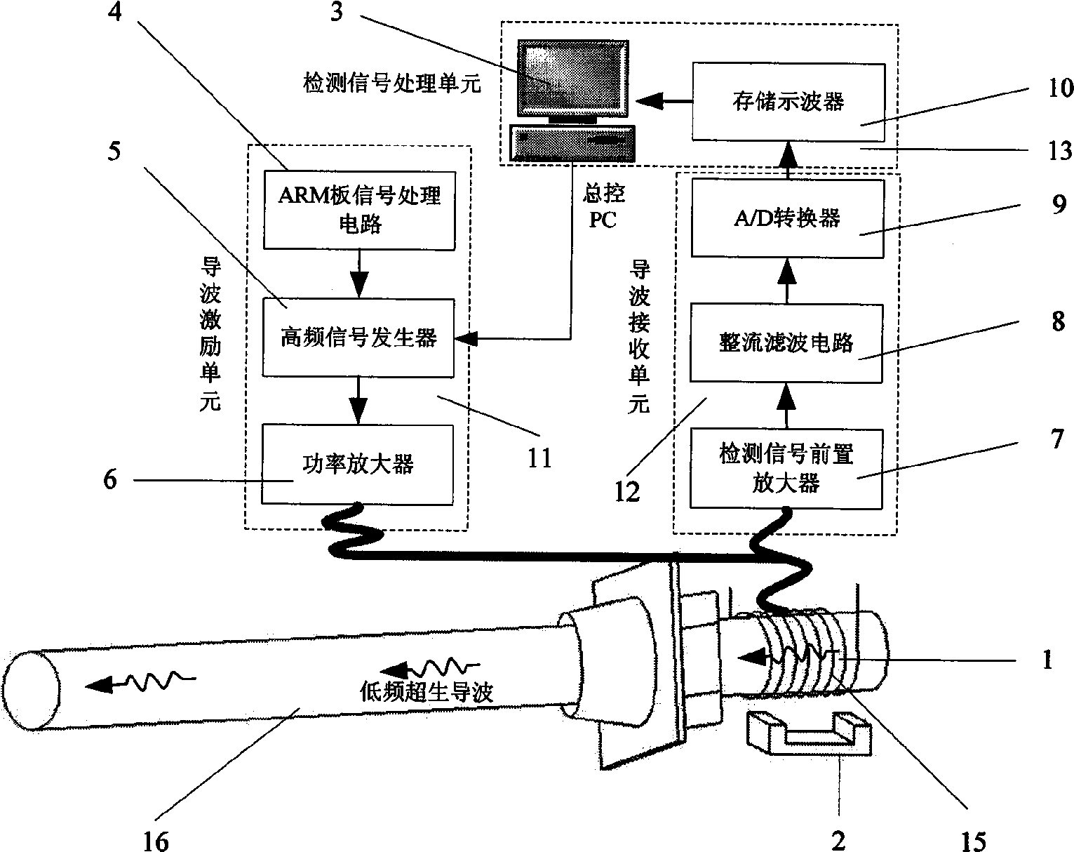
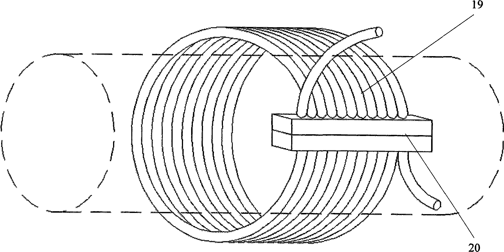
[0026] The detection principle diagram of the present invention is as figure 1 shown. Firstly, the magnetostrictive guided wave sensor 1 is installed on the free end 15 of the anchor rod to be tested, and 16 is the anchoring end of the anchor rod. The sensor does not need to be in contact or coupled with the measured anchor rod, and measures the distance L between the center of the magnetostrictive guided wave sensor and the free end surface 17 of the anchor rod 1 . Appropriate static bias magnetic field is applied within the scope of the free end 15 of the anchor rod larger than the installation position of the magnetostrictive guided wave sensor to make it magnetized. The static bias magnetic field 2 can be produced by a DC coil or a circular array magnet 23. place. The ARM board signal processing circuit 4 is connected to the control terminal of the hig...


PUM


Abstract

The invention discloses a ferromagnet magnetostrictive effect-based method for testing the length of an anchor rod, which comprises the following steps that: a magnetostrictive waveguide sensor is arranged on the free end of an anchor rod to be tested; a static bias magnetic field is applied at the mounting position of the magnetostrictive waveguide sensor; an exciting pulse signal is applied to the magnetostrictive waveguide sensor to excite mechanical vibration on the free end of the anchor rod; the sizes of the exciting pulse signal, exciting frequency and the static bias magnetic field are set to excite waveguides mainly in a longitudinal mode in the anchor rod; a receiving unit converts an elastic wave signal in a member to be tested into an electrical signal by using an inverse magnetostrictive effect, and after signal amplification, filtration and rectification, signal averaging and A / D conversion treatment, the electrical signal enters a test signal processing unit to test the actual length of the anchor rod to be tested. The method can realize the excitation and detection of ultrasonic waves in the anchor rod. The test signal contains information on the length and defects of the anchor rod and the actual length of a measured anchor rod can be measured accurately through the processing and analysis of a waveguide reflected wave signal.

Description

technical field [0001] The invention relates to a non-destructive detection method for ferromagnetic materials, in particular to a detection method for the length of an anchor rod based on the magnetostrictive effect of ferromagnets. Background technique [0002] Bolt anchoring technology is widely used in underground structural engineering (tunnels, caverns, etc.) and slope care in railways, highways, mining projects, etc. due to its characteristics of safety, speed, and low cost. In the process of use, due to various reasons, the bolt will have cracks, corrosion and other failure phenomena, causing potential safety hazards, and its health status needs to be evaluated regularly. Bolt anchoring is a concealed project, and it is difficult to manage and supervise during the construction process. Since the bolt is embedded in the rock formation after anchoring, the supervision unit cannot effectively detect its actual length. The length of the bolt embedded in the rock is one ...

Claims


Application Information

Patent Timeline
IPC IPC(8): G01B7/02
Inventor 吕福在唐志峰刘洋
Owner ZHEJIANG UNIV
Learn More