
System and method for fault diagnosis of traffic signal controller

A traffic signal and fault diagnosis technology, which is used in traffic control supervision, measurement using digital measurement technology, etc., can solve the failure of the fault detection function, cannot well meet the requirements of the working environment of the signal controller, and fails to detect faults. and diagnostics

Inactive Publication Date: 2009-09-30
INST OF AUTOMATION CHINESE ACAD OF SCI
View PDF0 Cites 31 Cited by
  • Summary
  • Abstract
  • Description
  • Claims
  • Application Information

AI Technical Summary

Problems solved by technology

[0003] Most of the existing traffic signal controllers pay more attention to the realization of the function of the signal controller in the design and production process, but less consideration is given to the fault diagnosis technology of the signal controller, which cannot well meet the requirements of the actual working environment of the signal controller
The signal controller with fault detection function generally does not have an independent fault detection module, but is integrated into the signal controller. Once the signal controller fails to operate, the fault detection function will also fail, and the function of fault detection and diagnosis cannot be achieved.
Moreover, the detection fault type is single, and generally only green conflict faults are detected

Method used


Image

  • System and method for fault diagnosis of traffic signal controller
  • System and method for fault diagnosis of traffic signal controller
  • System and method for fault diagnosis of traffic signal controller

Examples


Embodiment Construction

[0067] The fault diagnosis system and method of the present invention will be further described in detail below in conjunction with the accompanying drawings. It should be noted that the described embodiments are only intended to facilitate the understanding of the present invention, rather than limiting it in any way.

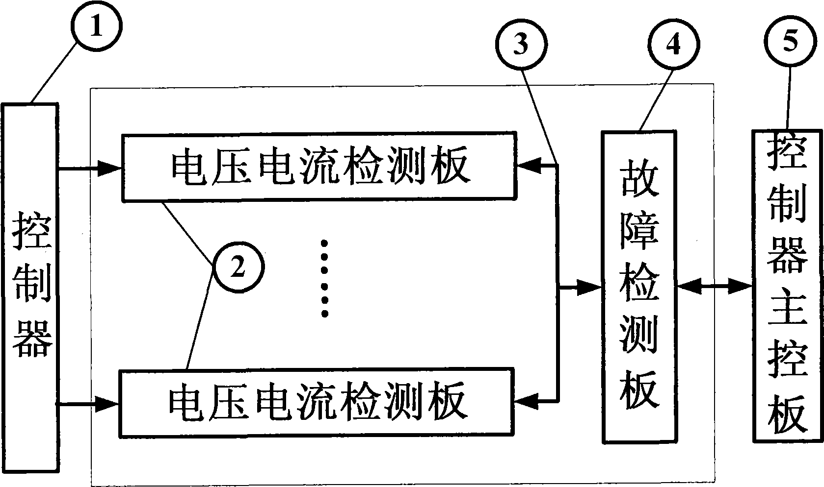
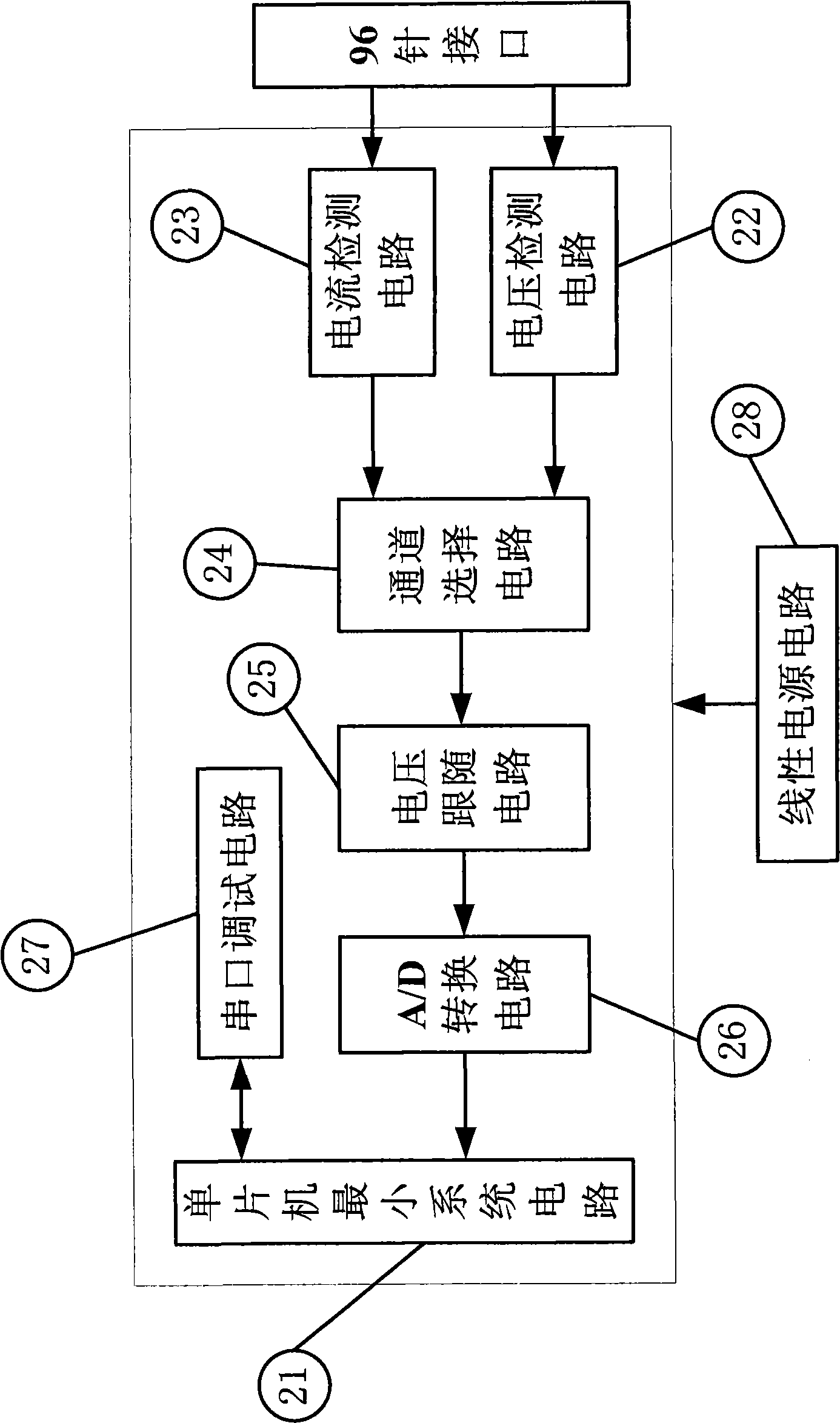
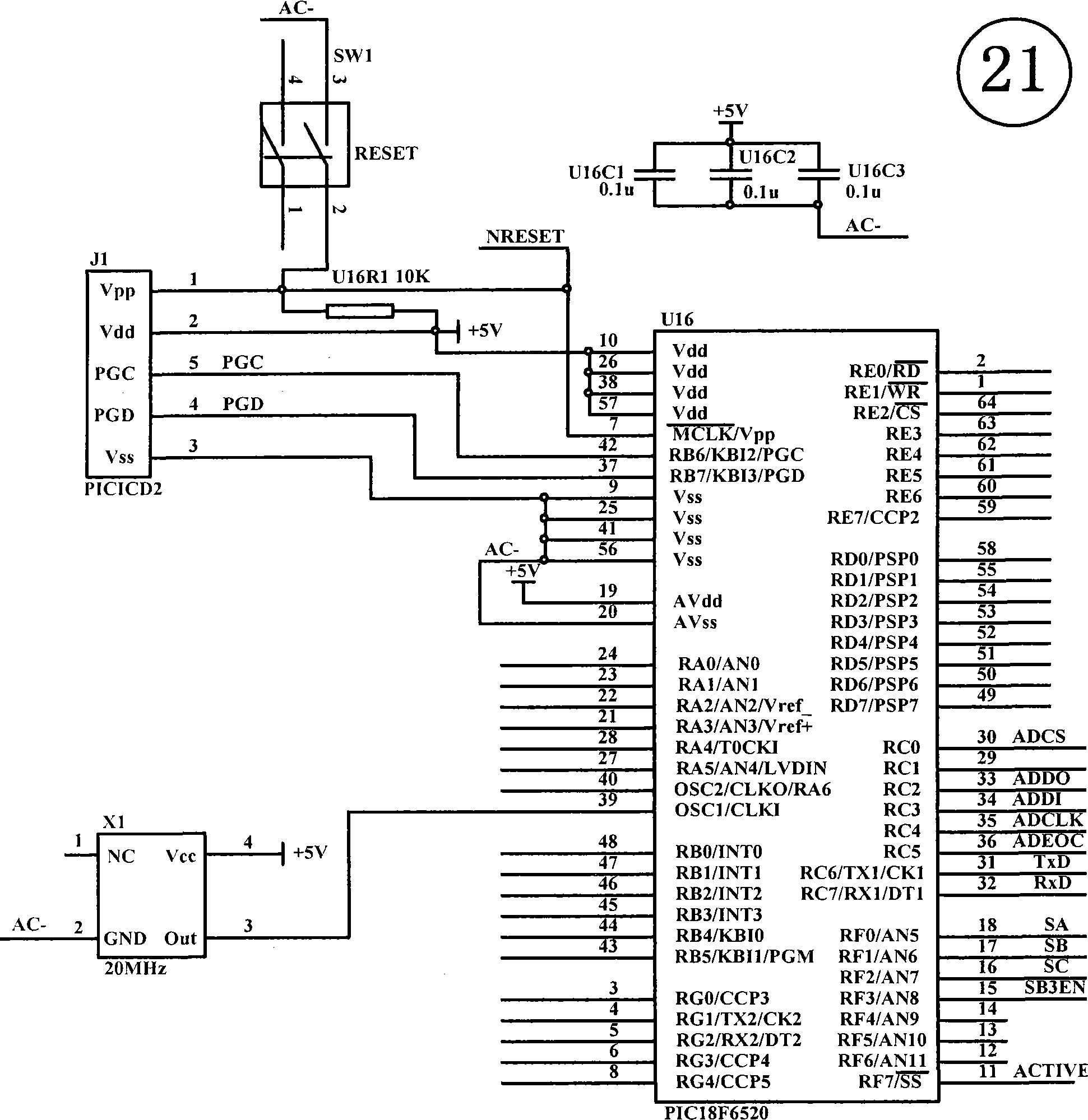
[0068] figure 1 It is a structural schematic diagram of a fault diagnosis system, including a fault detection board 4 and multiple voltage and current detection boards 2, the number of voltage and current detection boards 2 is determined by the number of signal lamp output channels of the traffic signal controller. The voltage and current detection board 2 takes the AC output of the signal controller 1 as input, and multiple voltage and current detection boards 2 are connected to the AC signal output end of the controller 1, and are used to monitor the voltage of each AC signal of the controller 1 and each The current of the AC signal of each channel is detect...


PUM


Abstract

The invention discloses a system and a method for fault diagnosis of a traffic signal controller. The method comprises the following steps: a fault detection board is connected with a plurality of voltage and current detection boards; the voltage and current detection boards are used for detecting the voltage and the current information of each path of alternating current output of the traffic signal controller, the fault detection board performs communication with each voltage and current detection board at regular time, searches the voltage and the current information and performs green conflict detection and other fault judgment for the traffic signal controller according to the defined rule in advance; under the unusual circumstance, a master control board of the traffic signal controller is warned, and the concrete fault type is displayed through an indicating lamp of the panel; if a serious fault occurs, the fault detection board provides an alternating current relay output signal to control the output of the traffic signal controller so as to switch the traffic signal controller to a flashing yellow state; and the invention provides the fault diagnosis system and the fault diagnosis method which are independent from the traffic signal controller, can perform real-time monitoring and fault analysis to the running state of the signal controller and fills the gap of the prior art.

Description

technical field [0001] The invention belongs to the technical field of intelligent traffic control and management, and relates to a fault diagnosis for a road traffic signal controller. Background technique [0002] The traffic signal controller is used for traffic light signal control at urban road intersections, pedestrian crossings and expressway entrances. It is an important part of the traffic signal control system for commanding and guiding vehicles. Its safety and reliability are directly related to traffic operation safety. Since the signal controller is installed at the intersection of the city, the working environment is harsh and it is susceptible to external interference, which may cause signal lamp failures, thyristor failures, etc. If these failures cannot be diagnosed and dealt with in time, traffic accidents may be induced and traffic jams may be caused. cause serious consequences. Therefore, it is of great significance to monitor the operation status of the...

Claims


Application Information

Patent Timeline
Patent Type & Authority Applications(China)
IPC IPC(8): G08G1/097G01R19/25
Inventor 王飞跃汤淑明李镇江姚庆明朱凤华黄武陵刘建庚
Owner INST OF AUTOMATION CHINESE ACAD OF SCI
Learn More