Low-voltage circuit breaker
A low-voltage circuit breaker and contact technology, applied in circuit breaker parts, circuits, electrical components, etc., can solve the problem that the upper contact does not play a protective role, and achieve the effect of improving breaking capacity and improving electrical life.
- Summary
- Abstract
- Description
- Claims
- Application Information
AI Technical Summary
Problems solved by technology
Method used
Image
Examples
Embodiment 1
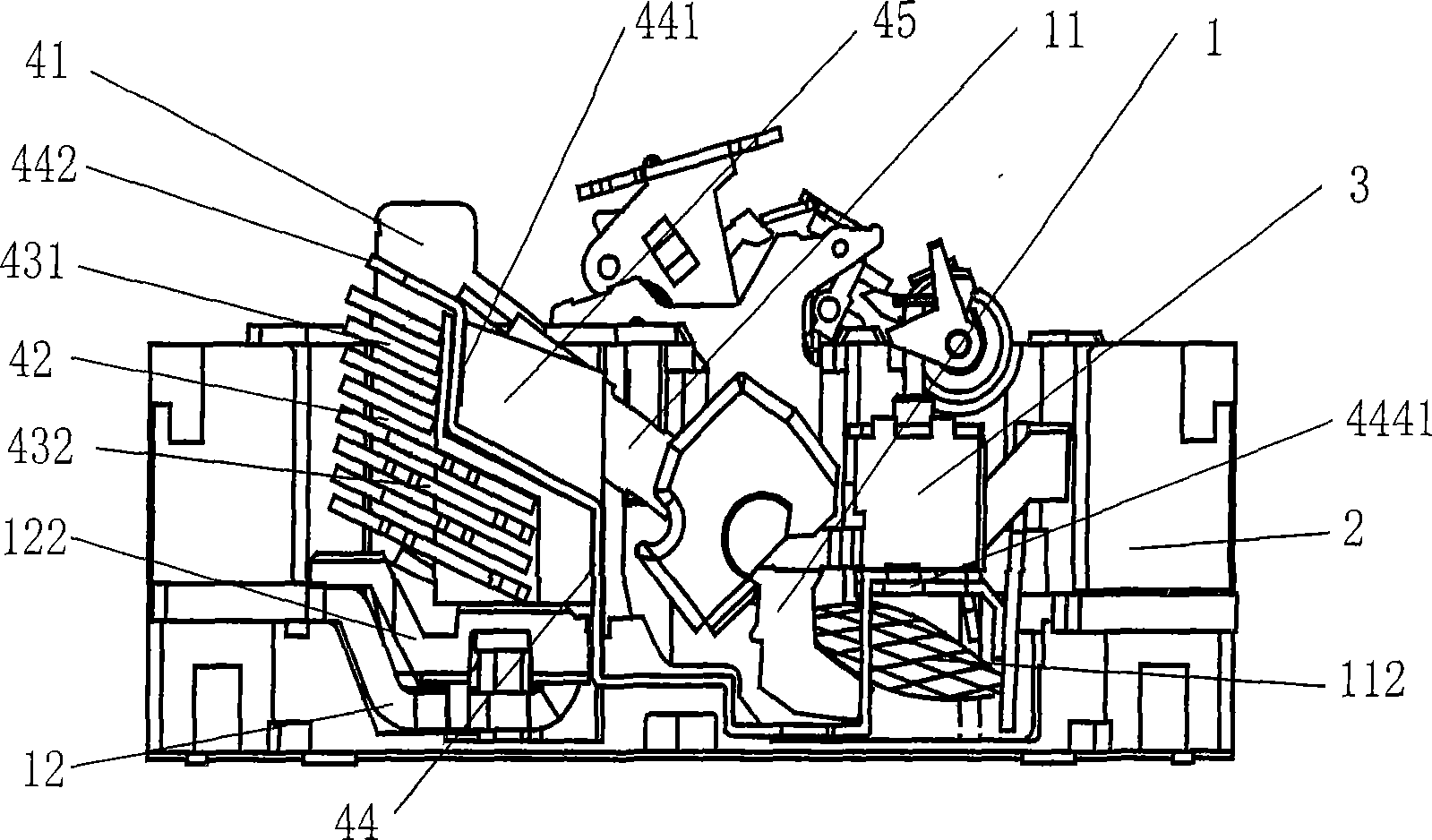
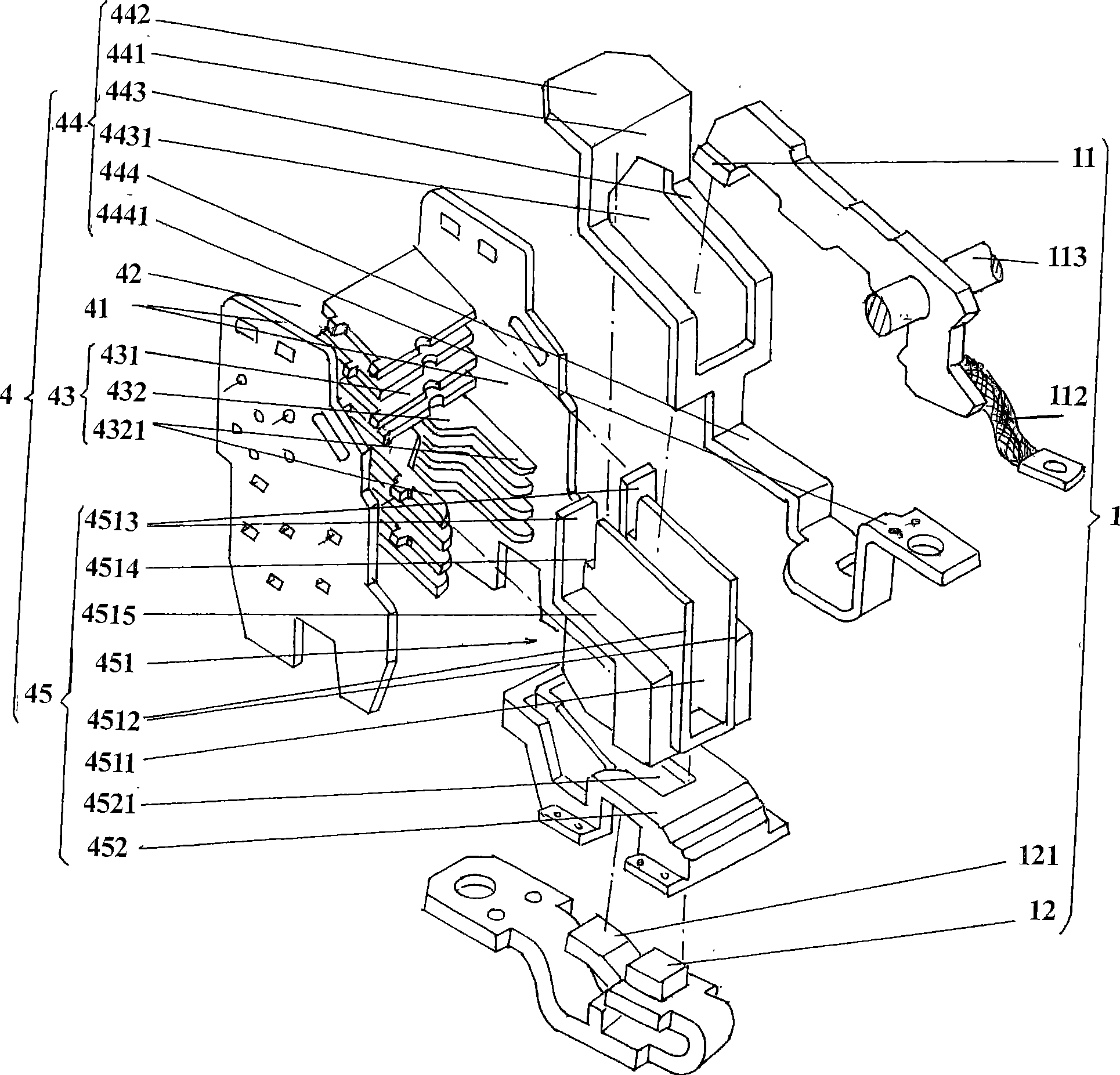
[0023] please see figure 1 and figure 2 , see first figure 1 , presents a known low-voltage circuit breaker, which includes a housing 2, a contact system 1 disposed on the housing 2, a tripping system 3, and a pair of arc extinguishing grid brackets 41, an arc extinguishing chamber 42 and a stack The arc extinguishing mechanism 4 formed by grid sheet 43. Please focus on figure 2 , the contact system 1 (also known as the contact mechanism) includes an upper contact 11 that is electrically connected to the aforementioned tripping system 3 through a flexible connecting wire 112 and is located at the bottom of the arc extinguishing chamber 42 and corresponds to the upper contact 11. The lower contact 12, as known in the industry, the upper contact 11 is connected with the operating mechanism of the low-voltage circuit breaker through the rotating shaft 113.
[0024] As the technical gist of the technical solution of the present invention, the arc extinguishing mechanism 4 ...
Embodiment 2
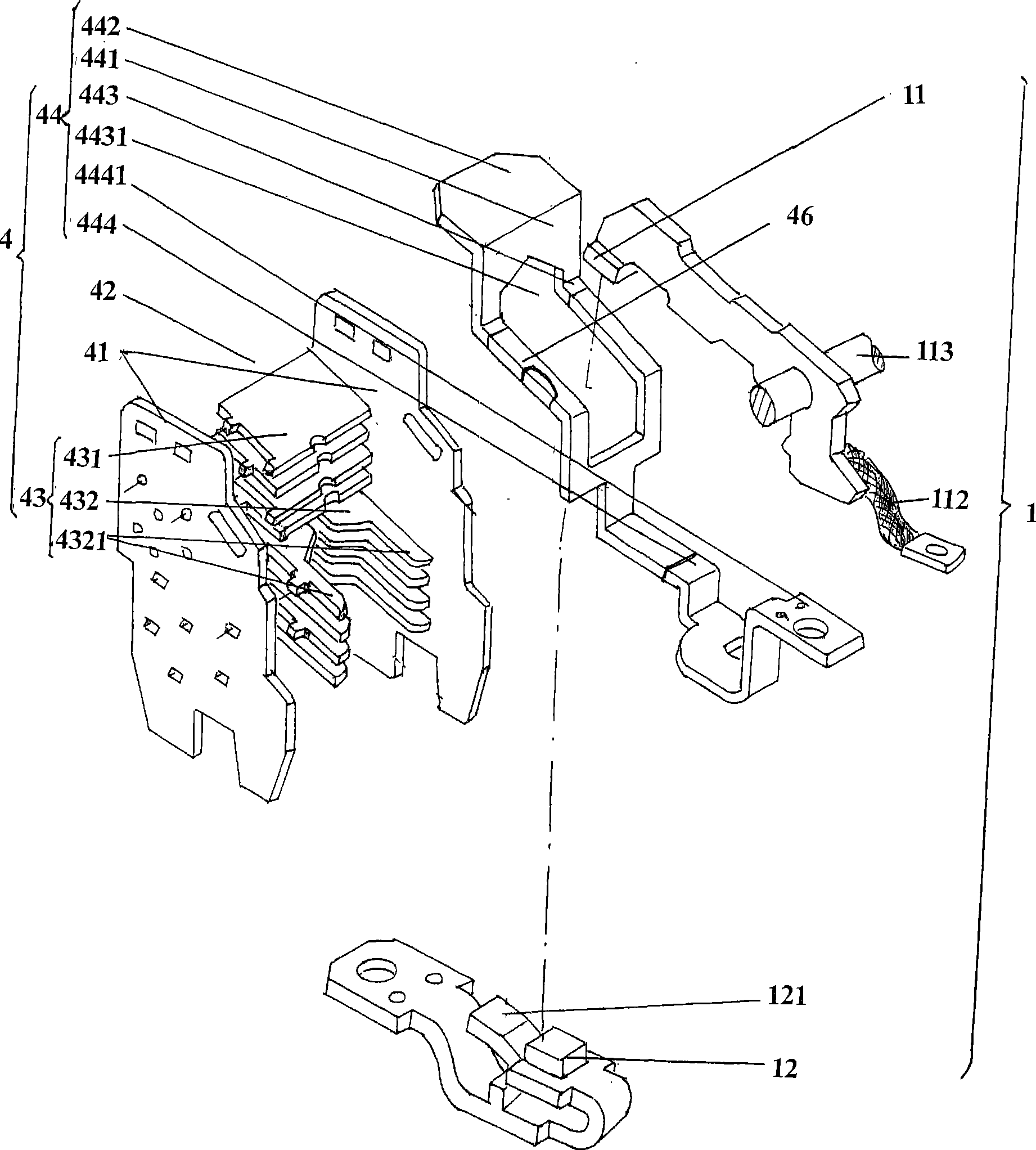
[0028] please see image 3 , in this embodiment, the insulating varnish 46 is selected as the insulating device, and the position of the insulating varnish 46 on the body of the arc striking plate 44 is the position corresponding to the arc extinguishing chamber 42 on the body of the arc striking plate 44, namely A pair of support arms 443 and a portion of transition plate 444 are shown. According to professional knowledge, the first and second arc striking surfaces 441, 442 are not allowed to be covered with insulating varnish 46, otherwise the arc striking function will be lost. Again, if the remaining parts of the arc running plate 44 are covered with insulating varnish 46 except the first and second arc running surfaces 441, 442, it is certainly feasible. The rest of the positions mentioned here include a pair of support arms 443, transition All of the board 444 and the electrical connector 4441, but considering the principle of economy, since a pair of support arms 443 c...
Embodiment 3
[0030] please see Figure 4 , the insulating film 47 is selected to take on the role of the insulating device. In this embodiment, a flame-retardant insulating tape is used as the insulating film 47, wrapped around a pair of supporting arms 443 and the transition plate 444 (a part of the transition plate 444) of the arc striker 44 )superior. Same Example This embodiment does not need to use the insulating support 45 composed of the insulating support body 451 and the support sleeve 452 as the insulating device like the first embodiment, and the rest are the same as the description of the second embodiment.
PUM
 Abstract
Description
Claims
Application Information
 - R&D
- Intellectual Property
- Life Sciences
- Materials
- Tech Scout
- Unparalleled Data Quality
- Higher Quality Content
- 60% Fewer Hallucinations
Browse by: Latest US Patents, China's latest patents, Technical Efficacy Thesaurus, Application Domain, Technology Topic, Popular Technical Reports.
© 2025 PatSnap. All rights reserved.Legal|Privacy policy|Modern Slavery Act Transparency Statement|Sitemap|About US| Contact US: help@patsnap.com


